Dobsonian
Contents
(n8vi's 12.5-inch f/5 dobsonian telescope)
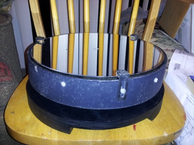
A friend of mine gave up on finding time to start his project to turn the pile of telescope parts he got off ebay into a telescope. The project has become mine. The parts I inherited were a 12.5-inch f/5 mirror, a metal cell for it to live in with a 15.5-inch outer diameter, a rack-and-pinion focuser with a bent pinion, a secondary mirror, and a spider vane assembly. Supposedly, he was supposed to receive a tube, but it never arrived.
The dobsonian is currently living near the middle of i3's west wall.
Astigmatism or miscollimation?
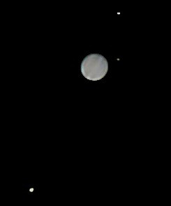
2012-10-08: Well, last night I saw The Ring Nebula from my own backyard (I figured it was too light polluted), took a bunch of imagery of Jupiter, and discovered my primary mirror has a fairly serious astigmatism. Now, astigmatism can be caused one of two ways - one is the forces on the primary mirror from the cell it's in, and can be fixed by removing the forces. This is often referred to as "pinched optics". The other source of astigmatism is a manufacturing defect annealed into the mirror. I believe this issue is the former, as I don't think this problem was there the first few times I had it out (although, perhaps I wasn't looking). Full report pending.
2012-10-10: I pulled the primary out and found it was a bit pinched in its cell, so I've backed off everything then verified the mirror cannot fall out of the cell, but can move slightly. I had it outside for several hours last night, then tried focusing a bright star again. I was unable, as before, to resolve much more than an amorphous fuzzy mass. Now, to me, the telescope looks perfectly collimated in a cheshire eyepiece, however, today I found a website which (in the right top corner) contains an image that looks exactly like what I'm seeing, which seems to indicate my collimation is off (though they have an SCT. I imagine the same thing applies to newts). I'll be trying to collimate with a star, a CCD, and a video monitor next clear night. I think what I might be learning here is that the primary is not correctly center-dotted (and/or the geometric center is not the optical center?)
2012-10-12: Clear night tonight, will be fiddling heavily with collimation using CCD and video monitor.
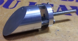
2012-10-17: Verified secondary holder centered in tube by removing secondary and sighting primary center dot through hole in secondary holder into which secondary mounts. I'm pretty positive I have perfect collimation and the issue remains. The current suspect is the secondary mirror. The secondary lives inside what could best be described as a soda can with a 45 degree cut through it, which has a lip on its 45 degree cut, to the inside of which is glued the secondary. It's the gluing of the secondary (with JB Weld, if I'm not mistaken, onto the reflecting (first) surface, again if I'm not mistaken) that makes me think the mirror is being bent out of flatness. I'm not sure how much success I'll have pulling the secondary out of JB-Weld, and a new secondary is about $150. The next clear night test will be to hook up the CCD and video monitor and try spinning the primary mirror cell in the tube with a star just out of focus (where it looks like a line at high magnification) to see if the orientation of the line follows the orientation of the primary. If it doesn't, I'm tearing apart and rebuilding the secondary holder (and if I break the secondary I can then confidently buy a new one), and if it does, I guess I just have a little cry about devoting three months of my life to building a telescope around an astigmatic primary (as there's no way I'll find a replacement that has exactly the same focal length, the optics market just doesn't work that way, and I might as well start over at that point).
2012-10-18: Was able to rotate primary mirror with scope fully assembled tonight. Doing this several times, I saw no change in the orientation of the astigmatism. This is good news! Besides telling me that the primary is definitely not pinched (I would not be able to rotate it if it was), it tells me the primary is not the primary contributor to the astigmatism. Looks like I'm building a new secondary holder.
2012-10-22: Fiddled with Newt-Web for a bit to figure out what size the secondary for this thing should be, then ordered a new secondary mirror. May have proceeded slightly hastily here and may have undersized the mirror. Whatever, it was $40, and if it shows up unbent, it'll still look better.
2012-11-10: Today I discovered that the warping of the field of view that I'd been seeing in the telescope may have coincided with the replacement of the secondary mirror, but the new secondary is not the cause - the eyepiece is! Apparently I was doing solar projection with the wrong sort of eyepiece and actually melted part of the lens. Replacement of this eyepiece with another I happen to have found from my younger days which is basically the same eyepiece results in non-warped fields of view again.
2012-11-11: Yesterday's discovery combined with today's completion of the replacement secondary holder have re-energized this project. Granted, completion involved adding three springs to something Steve basically made while I looked on and tried to learn a thing or two. It's gorgeous and you'll find a picture of it near the bottom of the page. Night of 11/11: tested with non-melted eyepiece and new too-small secondary (attached to Steve's new secondary holder), all signs of astigmatism gone! Stars at high magnification still look strange, but Jupiter is crisper than ever! Curiously, I'm now seeing diffraction spikes on bright stars, which is something I've never seen before. The new secondary holder also is way easier to collimate than the old one, so that too is awesome. Just need to get a properly sized (now that I know the formulas, it's about 2.6 inches minor axis) secondary. Can't wait to see Saturn in this thing, and that should be up in the mornings soon.
Previous incarnation
In trying to figure out why on earth my secondary is JB-welded to its holder around the entire edge, I've come across a few pictures that look like my spider assembly, and a few pictures that look like my original mirror cell. All of the telescopes I've found like this so far are made by Cave Optical Company, which appears to have a bit of a cult following. My mirror also has a sticker on the back proclaiming it to be aluminized by Pancro Mirrors, Inc, which is purportedly the company Cave had aluminize all their mirrors. I'll photograph the outer edge of the primary next time I have it out of it's cell.
If the primary is from Cave, it's quite possibly due for a recoating, as Cave folded in the early 80s.
Construction Tasks
OTA (optical tube assembly)
- determine focal length of mirror by pointing it at a white board next to a light source and changing its distance until the reflection of the light source on the board is in focus. Divide this distance by two to get the focal length DONE: 65 inches, which makes this 12.5" diameter mirror f/5
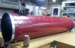
- purchase concrete pouring tube with enough inside diameter to allow cell for 12.5-inch mirror to move around a bit with a length of the focal length of the mirror or longer. DONE. 14 inch ID, 72 inch length
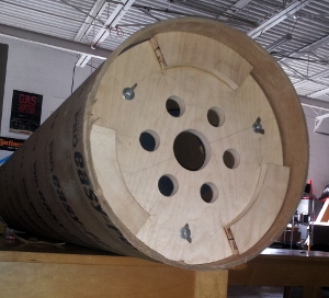
- build new mirror cell back ("tailgate") for new tube inside diameter. Drill holes for ventilation, plus holes to match the asymmetrical tuning screws on the cell front. Add locking screws. DONE, although the locking screw heads and tuning screw heads collide, but perhaps I'll replace them both. I'd much prefer replacements with knurled circular heads. Maybe I'll make them ...
- drill focuser hole, with notch for rack DONE
- drill holes for and mount secondary mirror DONE. It even collimates!
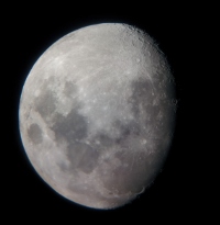
- Set primary in back of tube, lock it in place with shims, and move the mirror around until something several miles away comes into focus with the focuser at midrange. Do this for a number of observers and average the results. Try it with several eyepieces. A good site to try from is the parking structure at work, from which the Detroit Zoo watertower, five miles away, is visible. System test done, wedged primary mirror in with wood shims and viewed moon (see photo below). Mirror was almost a foot into the tube, however it was still not far enough in for the high power eyepiece (9mm with 2x barlow) to focus. DONE, 31 Aug. Found align point on my lunch break, marked with pencil, checked focus of detroit zoo water tower and a prominence on a roof about 1.5 miles away from the top of work's parking structure. Looks good. Later got a good view of Venus, primary still held in with shims.
- about now would be a good time to make a cover for the end of the tube, so when the primary is installed, we can keep dust off it. In progress as, of course, the last step
- buy a telrad, they're cheap! DONE, arrived, looks pretty awesome.
- install mirror in the average spot given all the marks from different observers DONE. Looks quite good with the cell held in place with three brass screws sitting in brass grommets. also, this averaging stuff isn't necessary, different eyeballs aren't that different, but different eyepieces are. I checked with a 25mm eyepiece and a 9.5mm eyepiece in a 2x barlow.
- buy a second smaller tube and experiment with what's necessary to paint it and make it not look like crap. Actually experimenting now with a piece cut off the end of the tube when it was cut to length. May or may not use gap filler to remove the spiralling on the outside of the tube before primering
- dismantle optical tube assembly and cut the tube to length. DONE
- Sand the inside to rough up the light wax coating on the inside, and paint the inside matte black DONE. Not pleased with how it looks, I used far too course of sandpaper and tore up the inside of the tube, but functionally it should be okay. May sand and repaint. looked at this again today, it looks fine ... hell, the mild torn-upness of the tube probably baffles light better
- fill the gaps created by the spiralling paper that makes up the tube with wood gap filler (got this idea from model rocket builders)DONE. Probably a bad idea, I don't have the patience to sand this properly, so it'll probably look worse than it would have without gap filler
- sand that DONE
- prime the outside of the tube had to stop five cans of primer in, still not totally uniform though
- sand that DONE. Now looks much more even.
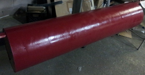
- paint the outside of the tube DONE
- Clearcoat the outside of the tube, depending on results with test tube DONE
- repaint the inside of the tube because clearly there wasn't enough masking while painting the outside DONE. Used special low-reflectivity paint. Looks good.
- figure out how to do tube rings, ie, metal rings at the top and bottom of the OTA to prevent denting and tearing Apparently i3 has a machine that magically turns strips of metal into rings, and I have a shop open on Saturday right next to my house that sells metal strips. Just need to decide width. DONE. 8.5 feet of aluminum from metal mart ($10) -> ring roller -> Sexton Enterprises for welding ($15) -> wire brush surface -> looks pretty awesome
- reassemble tube DONE. Sitting on the west wall at i3 with a plywood sheet on top of it because I still haven't gotten around to making a dust cover.
Dobsonian-style ALT-AZ Mount
- figure out bearing surfaces Well, the standard dob bearing is Teflon against ebony star laminate, right? Well, buying a sheet of laminate in normal person quantities is a little less than a hundred bucks. You can sample an 8 x 11" piece, but that's a little small for my purposes. [This] place has some smaller quantities though. DONE - teflon on smooth laminate works fine, despite what people say. Also, Dave A. had some sitting around. Thanks Dave!
- perhaps acquire a small piece of Teflon and wander into countertop places looking for a good surface to run the Teflon on for the bearing surfaces of the mount how about find teflon in my living room? I have found a vinyl LP for the azimuth bearing. Contemplating brushed aluminum for the elevation bearing. DONE, see above
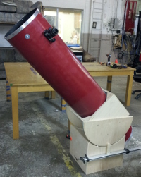
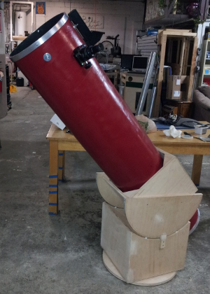
- build a box around the tube with the semicircle alt bearing surfaces attached to the center of either side. Slide the box until the bearing surfaces are at the center of balance. Put a screw or two into the box from the inside of the tube. Box built, thanks to the help of Dave A with shopping for the right kind of plywood, rabbeting, and not killing myself with a tablesaw. DONE. Balanced, laminate applied to bearing edges. Thanks again Dave A.
- Attach hefty brass handle to top of tube box. DONE
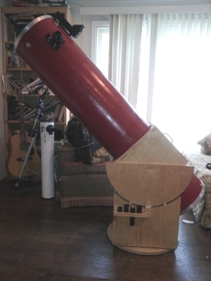
- build the alt mounting, ensuring it is tall enough such that the telescope can point straight up. This means that the balance point will have to be sqrt((balance point)^2+(tube radius)^2) high, for the most forward-heavy configuration. DONE. I scaled it so that the eyepiece is at standing eye level when the scope is pointed straight up. You can't escape Dobson's hole though, as you'd have to lie down to view below 20 degrees. May be augmenting rocker box height prior to worrying about azimuth bearings. Rechecked, this time allowing for observing from a chair. It's good from 90 to 20 degrees, with a transition from standing to sitting at around 45 degrees. I call that damn near perfect.
- build the az mounting, with some sort of screw or bolt protruding from the center of the bottom surface through a hole in the center of the top surface. Possibly we can mount a gear or something here later for motorization. The floor of the rocker box will be square and will rotate on a round ground board so that the furthest protruding part of the base is always a consistent distance from the operator's feet (no surprise trip hazards!). The ground board will have three feet. DONE. Added a floor board to the rocker box last night after I realized how this should work. Ground board added with teflon pieces into a vinyl LP. I now have functional bearings on both axes. Three feet added, tough rubber, wobbbled a bit much, switched to harder plastic, working well.
- attach two handles to mount (Nope, there will be either one monkey handle or one brass handle up front). DONE. One brass handle
- stain and varnish the mount or whatever (I will be clearcoating. Nothing more, nothing less.) DONE. Coat seems a bit light after four coats, may recoat
Completion
- Install telrad. Line it up, once again, by lying the tube flat and pointing at terrestrial objects. DONE. Lined up on the moon then slewed to Vega; Vega was then immediately visible in 9mm eyepiece with no correction. Easiest viewfinder I've ever used.
- FIRST LIGHT (next clear night after this) DONE. Split Mizar, checked out Albireo, the moon again, M45, and Jupiter. I have since seen Venus, M57 and M42. M42 looks amazing in this thing (it has a visible green tint!). Also caught a glimpse of VO-52 (a half-meter cube about 600 miles away) while looking for M31 (which I finally saw this past weekend, along with M110, from a small town near Jackson, Michigan).
- keep fiddling with collimation until it actually looks right Finally got it! I bet stars don't look oddly crescent-shaped in this thing anymore! Now I just need some clear weather so I can star test
Future targets
Keeping a list of these may be useful, as the way magnitude is calculated for deep sky objects is weird. You may be able to see a magnitude 9 nebula, but not a magnitude 3 galaxy, for example. These things are magnitude <10 and angular size <30 arcminutes
- I've seen the cloud bands on Jupiter without a problem, might try for the red spot. Jupiter rotates once every ten hours, so it should come up often.
- NGC253, the Sculptor Galaxy, mag 7.1, 25'
- M1, Crab Nebula, mag 8, 6'
- NGC2392, Eskimo Nebula, mag 10, 42"
- M44, the beehive cluster, mag 3.1, 1 degree 35'
- M65, M66, two close galaxies mag 9 and 9.3, 8'42" and 10'
- NGC2903, Galaxy, mag 8.9, 12'
- NGC2244, Rosette Nebula mag 9, 13'
- M20, Triffid Nebula mag 6.3, 29'
- M33, Triangulum Galaxy mag 5.7, 1 degree 2'
Afterthoughts
- eyepiece rack on the eyepiece side of the rocker box. DONE. Looks good
- dust cover. I know it's listed above, but it's waited until now to happen, and I'm working on it. started building one out of wood, then my mother actually offered to make one out of some sort of sewed fabric. I think this is a better idea, and I don't mind outsourcing :)
- aperture stop. This thing gathers so much light from Jupiter and Venus that I end up with washed out contrast. I can either up my magnification (and deal with impossible tracking and focusing) or stop the aperture. An aperture stop takes the diffraction effects of the spider vanes out of the picture too, but I have yet to actually see diffraction spikes in anything but a photograph. I'm working on the stop too, as it starts out with the same 14-inch diameter circle of thin plywood like the dust cover. Started making this out of wood too, perhaps this is also better made from fabric, looking into this another solution is higher magnification, which means more difficulty in tracking as the earth rotates. The solution to that is wider apparent field of view, and the standard for that is Nagler eyepieces in the >$300 range. I have, however, recently found these things, which are less than half that price. Hey wait a minute, this supplier is in Mount Clemens (about 20 miles away) ....
- filters. Need to get some of these and see if it doesn't help contrast on Jupiter at full aperture, light pollution and DSOs, etc
- solar filter. Likely this will be an aperture stop with some mylar glued to it. I'm going to test a lot with the aperture stop first though to ensure I can make one that doesn't fall off.
Accessory projects
- This focuser is a piece of crap. I may build a crayford to replace it, quite likely using an old printer roller or something, with teflon backing rather than back rollers. See here and here.
- The eyepiece goes from a foot above ground to my eyelevel standing. I may build a denver chair. See here. A fellow with whom I am acquainted in the Dearborn astronomy club built a ladder type thing on the back of his, I may do this also.
Possible Mechanization
The following steps may or may not happen if I decide I like poncet platforms, which is definitely a possibility.
- write code that fits in an AVR or MSP430 that can pull date and time from a GPS and convert that time into an posix-style integer and back, and can pull lat and lon and convert them into radians and back. DONE
- write code that converts RA and DEC to ALT and AZ for standalone earth rotation track mode MOSTLY DONE
- find specs for a scope control protocol full-sized stellarium supports DONE: Meade's sucks, I'm using celestron's
- make the above happen inside aforementioned AVR
- talk to Steve about motorization
- design a board for this uC to live in with motor control and GPS hardware
- provide serial access to this board through a header that can accept [this] board.
- produce a small similar board with an RJ45 connector on it to do serial in a cisco-style connector
- learn to code for android STARTED, I need to put more time into this
- design basic keypad controller for android that transmits celestron-style commands to the board over bluetooth
- either buy [Sky Safari Plus] or talk to the [stellarium mobile] people about helping add a scope control module
Tube
I bought a 14-inch ID cardboard concrete pouring tube for this. I was unable to find anything with a 15.5-inch ID, so I needed to rebuild the back of the mirror cell (see below).
The next steps of building this behemoth will all be centered around the tube - sanding the light wax coating off the inside of the concrete pouring tube and painting it matte black, drilling the focuser hole, installing the spider vane assembly and installing the primary mirror. After all that's done, I'll be tearing it all apart and painting the outside. And all of those steps contain fiddly substeps that involve figuring out placement of things. And possibly using a few shims.
Cell/Tailgate (Primary mirror mount)
I rebuilt the back of the mirror cell out of birch plywood, which I painted matte black. This was a most educational process in which I learned that pine plywood is terrible, beam compasses are awesome (the tailgate measurements were done solely with a compass), oil paint is for people who know what they're doing (I just grabbed the first thing that said matte black), wood glue is pretty sweet and easy to use (I attached three pieces on the back of the tailgate to make hitting the tailgate with the screws that will attach it to the tube easier), and that despite how imprecise hole saws look, noone can tell at this scale.
Spider (Secondary mirror mount)
I fretted about drilling the focuser hole and spider mount holes in my pristine tube for quite a while. Turned out it was quite easy - first, I sanded the edge of the tube flat and checked it with a square and a flat piece of board. Then I drilled the eyepiece hole one radius' distance from the edge, with a urethane foam mold of the tube's inside behind the drill bit to prevent tearout. I then filed out a notch for the rack of the rack-and-pinion focuser to fit in. I laid the spider on the outside of the tube to figure out how far back from the focuser hole the spider mounting screws would go. Then I tied a piece of string around the tube, measured all around to ensure it was the same distance from the end everywhere, pulled it off, folded it into eighths, hit one side with a sharpie, and put it back on. Now I had sharpie marks every 90 degrees. I remeasured everywhere to ensure the string was again the same distance from the end everywhere, and drilled the holes. The springiness of my spider vanes eased installation. Successes that surprised me at this stage: I didn't ruin the thing by drilling anything in the wrong place, the secondary doesn't bounce all over the place, and the focuser draw tube fits perfectly in the hole I drilled.
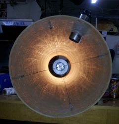
Another thing I learned here is that collimation of the secondary mirror is likely much more easily done without the primary installed, and instead with a light at the end of the tube. (I made a quick collimation eyepiece out of the top of a soda bottle and some masking tape with a hole poked approximately in the middle)
A recent idea I had was to make four small notches in the cell end of the tube. I could then remove the primary and insert two pieces of string (which would cross in the center of the tube, right?) to align the secondary.
