Simple hack for a quiet morning

I usually see big, wacky, catchy projects on blogs like these.Ā  Well Iā€™m here to remind you that small, commonplace, everyday hacks are just as important, especially during times of stress. Making or modifying something to make your life easier can be every bit as rewarding as making a giant installation or rolling art project.


Our cat gets a quarter-cup of food every morning.Ā  I have a half-cup scoop reclaimed from a box of protein powder.

Youā€™ve heard the joke before, about a partially filled glass? The optimist says itā€™s half full, the pessimist says itā€™s half empty, the engineer says itā€™s twice as big as it needs to be.

Iā€™m an engineer.


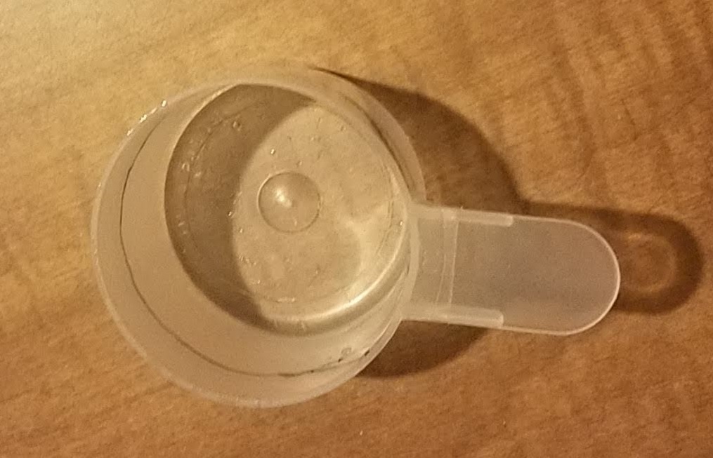
Here we see a perfectly unassuming 90cc scoop.Ā 

Scoop before alteration

Scoop before alteration

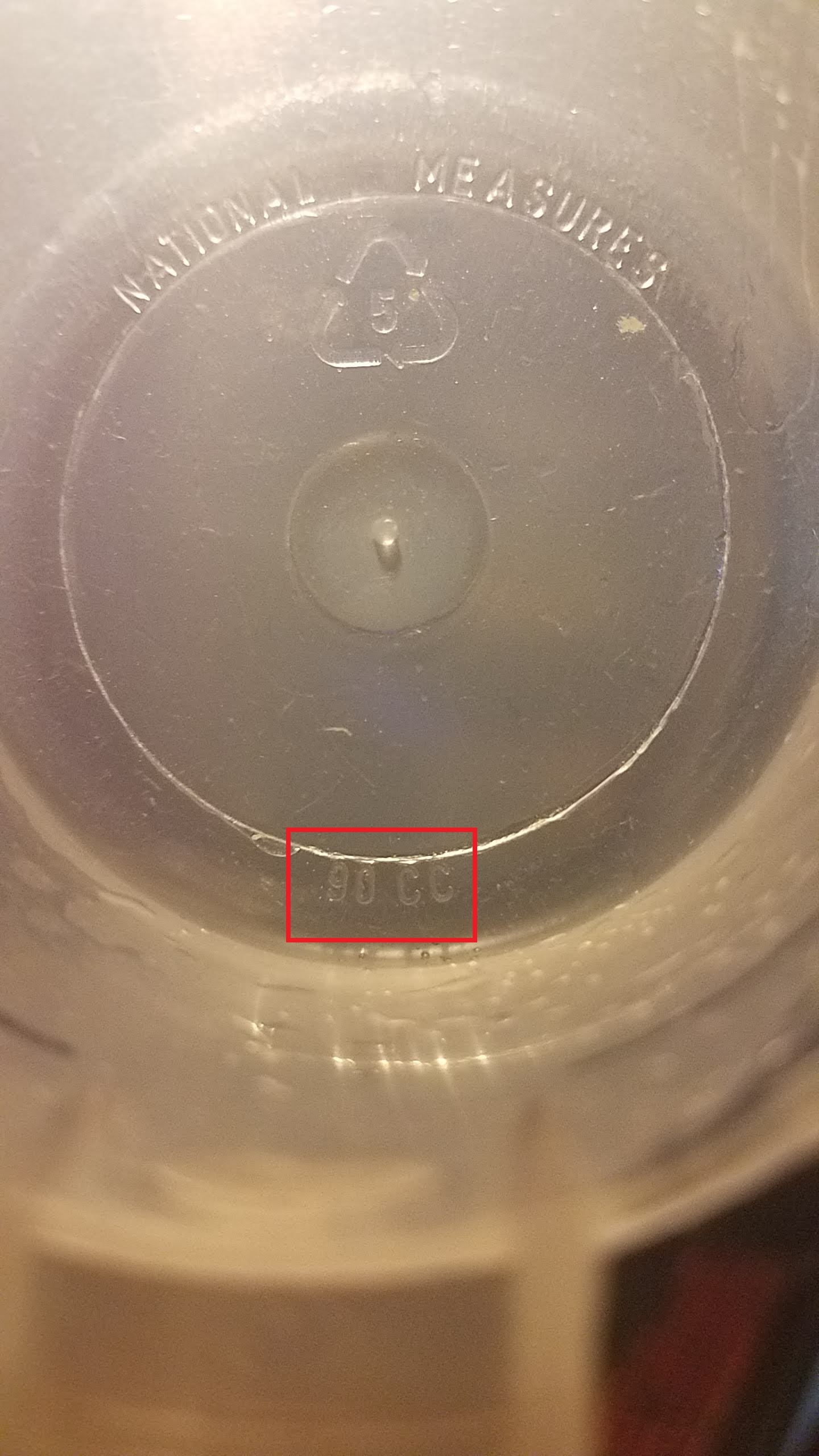
I know itā€™s 90ccā€™s because it says so.

90cc

90cc

We need a 45cc scoop. We do not have a 45cc scoop. They sell these, as itā€™s basically a Ā¼ cup, but I am disinclined to spend money, plus certain world events are extending shipping times and making a run to the store problematic.


Modification time!


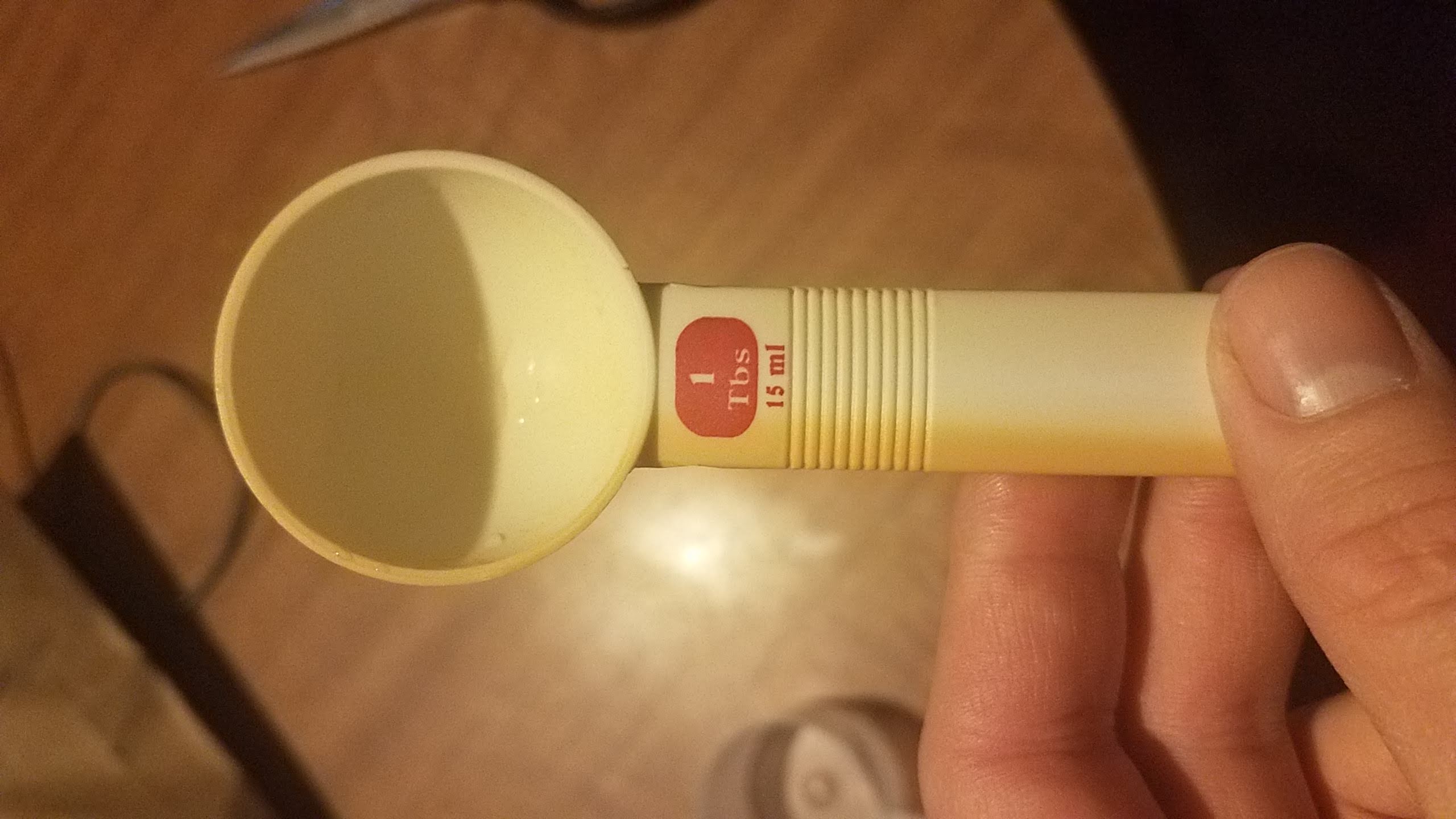
I found an appropriate measuring device, in this case a tablespoon (yes my tablespoons have metric on them, however approximate).Ā 

Tablespoon 15ml

Tablespoon 15ml

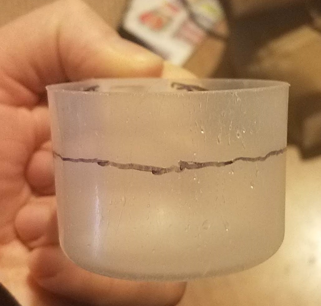
I measured 3 tablespoons of water, or about 45cc (cc and ml are basically the same thing), and traced the water level to give me the desired height of the cup.

Water line marked

Water line marked

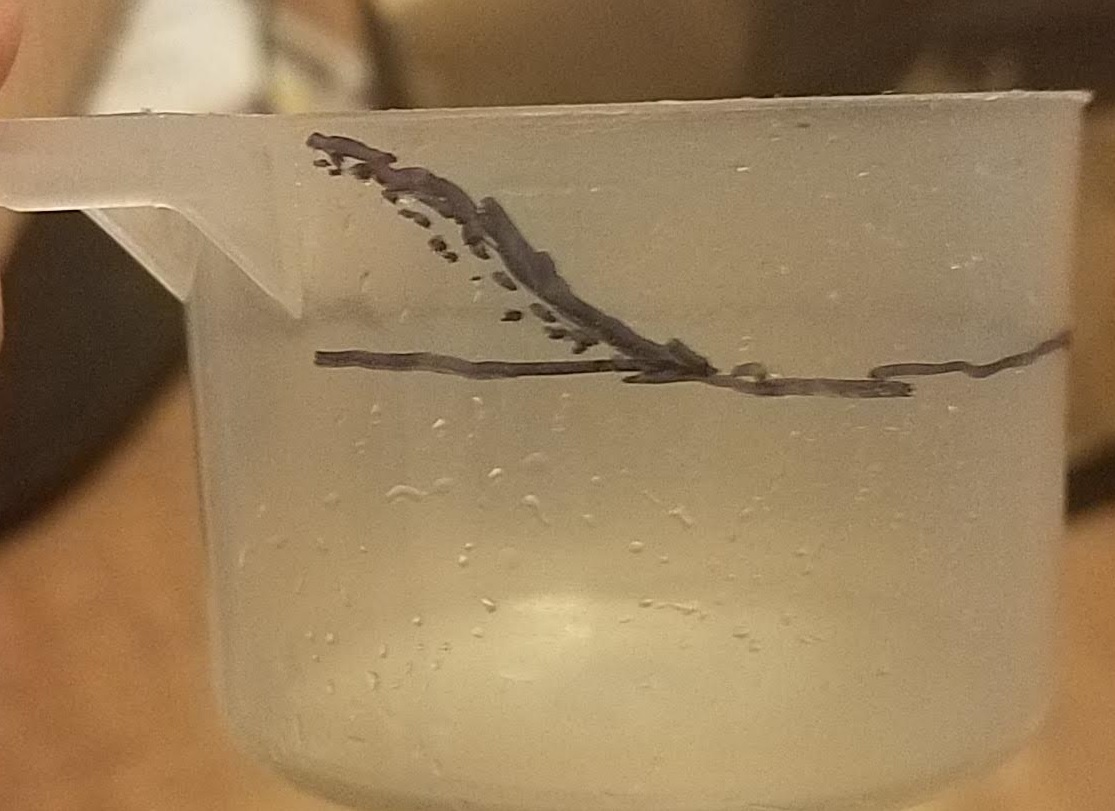
To make sure the handle didnā€™t get too floppy, I also drew in these supports on the side.

Lines for handle support

Lines for handle support

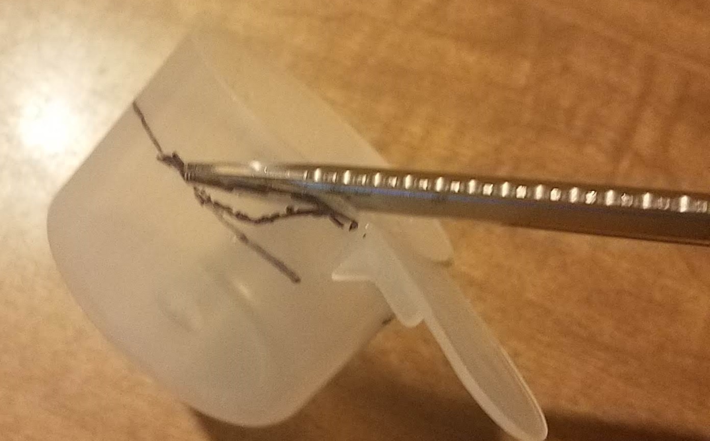
Then it was just a matter of using a pair of scissors to trim off the excess.Ā  It would have been way better to use a smaller pair of craft shears, but big olā€™ kitchen shears is what I had handy, so thatā€™s what I used.

Snip snip

Snip snip

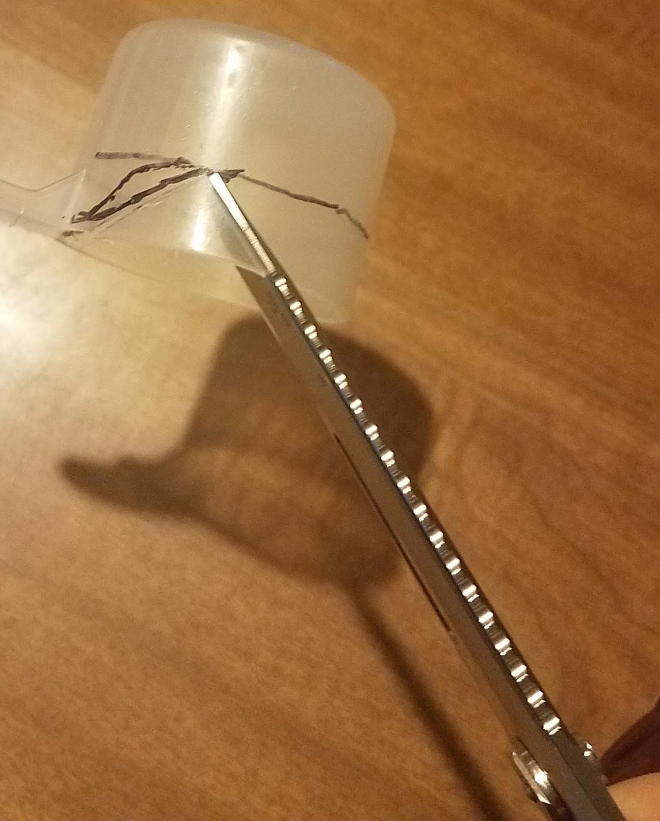
If you start off cutting a notch out, you can get the big scissors parallel to the cut.

Notching

Notch cutting

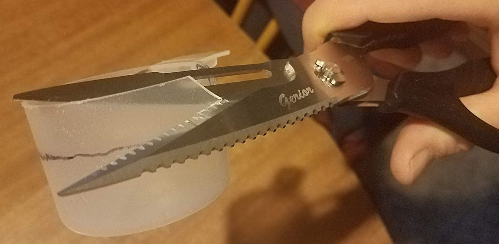
Make sure to cut above the line! That is, leave a little extra so you can finish it off nice.Ā  You can always take off a bit more, but adding it back on is a whole ā€˜nother level of complication you donā€™t need.

Cut above the line

Cut above the line

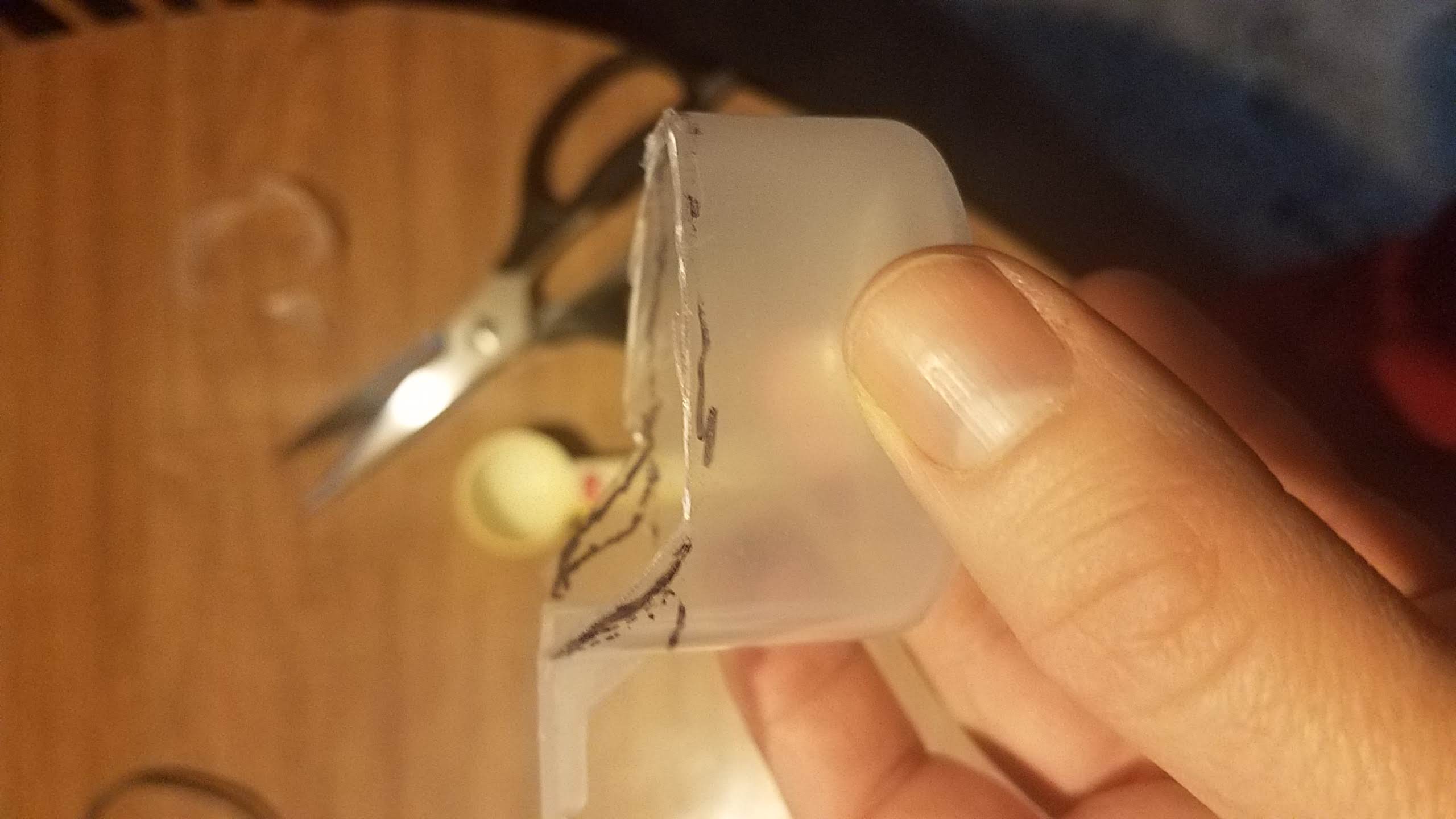
Leave enough extra for finishing

Leave enough extra for finishing

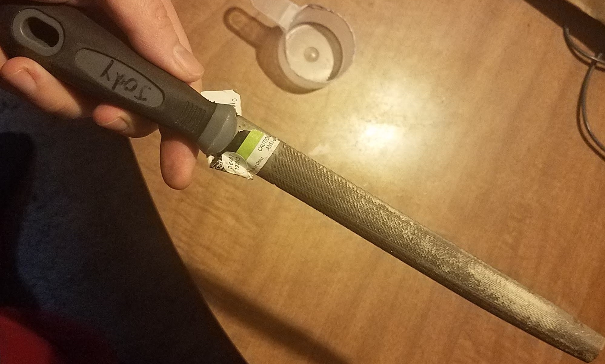
With the shape roughed out, grab a piece of sandpaper, or a nail file, or, in my case, an actual general purpose file. Itā€™s what I had lying around.

hand file

Hand file

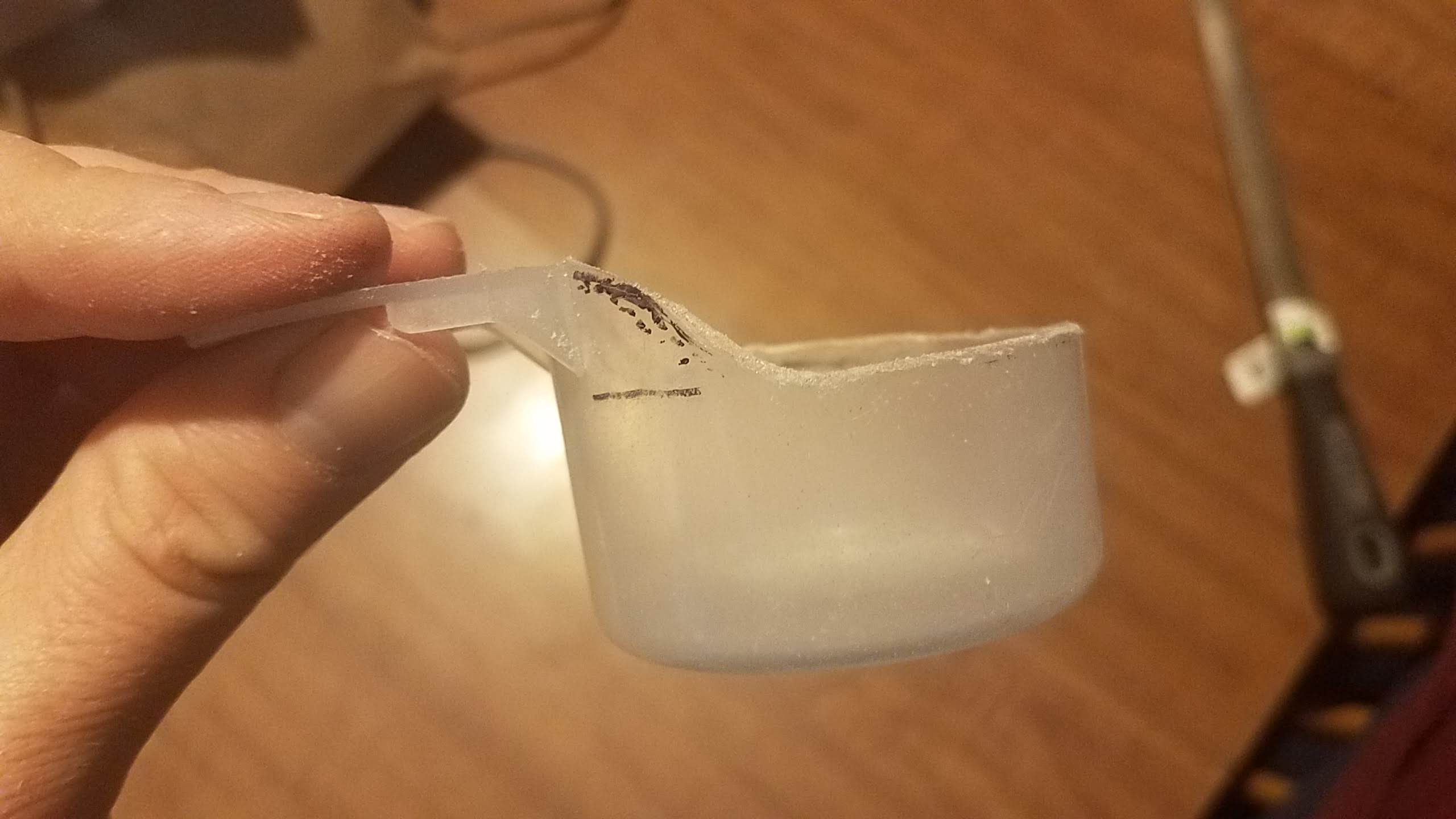
Use the scissors to trim down any big protrusions or bumps, then use the file/sandpaper to bring it down to the final shape. If you have a finer grit, you can use it to give a nicer finish, but I just kinda burnished it with the handle a bit. Good enough to scoop cat food with! (Warning: filing plastic will make a mess, and that mess will include micro-plastics to one degree or another. If thatā€™s something that bothers you, do this outside, or over a trashcan. Wear whatever PPE you feel you need, assuming you havenā€™t already donated it all to your local hospital. I did it on the back stairs with a strong breeze blowing so I didnā€™t breathe in any of the dust.)

Finished 45cc scoop

Finished 45cc scoop

Tada! A 45cc (ish) scoop! No more guessing on the cat food, just one scoop and good!Ā 


Took longer to write this post than it did to make the thing, but I felt it was important to remind you, making is about the little things too.


Stay sane in there people!

Ham Radio Mobile Install

Preamble

I am a simple girl. I like little cars. I like sporty cars. I like putting my foot down and zoomy happening. I also happen to like mobile radio operation. This poses a number of packaging challenges; for some reason, no one is building small, sporty cars with ham radio operation in mind.

About a month ago, I totaled my car. RIP Matilda; she died valiantly protecting us, and rides on to Valhalla. Matilda was a 204 Mazda3 s Grand Touring with the tech package, and around 136,000 miles. (HATCH LYFE)
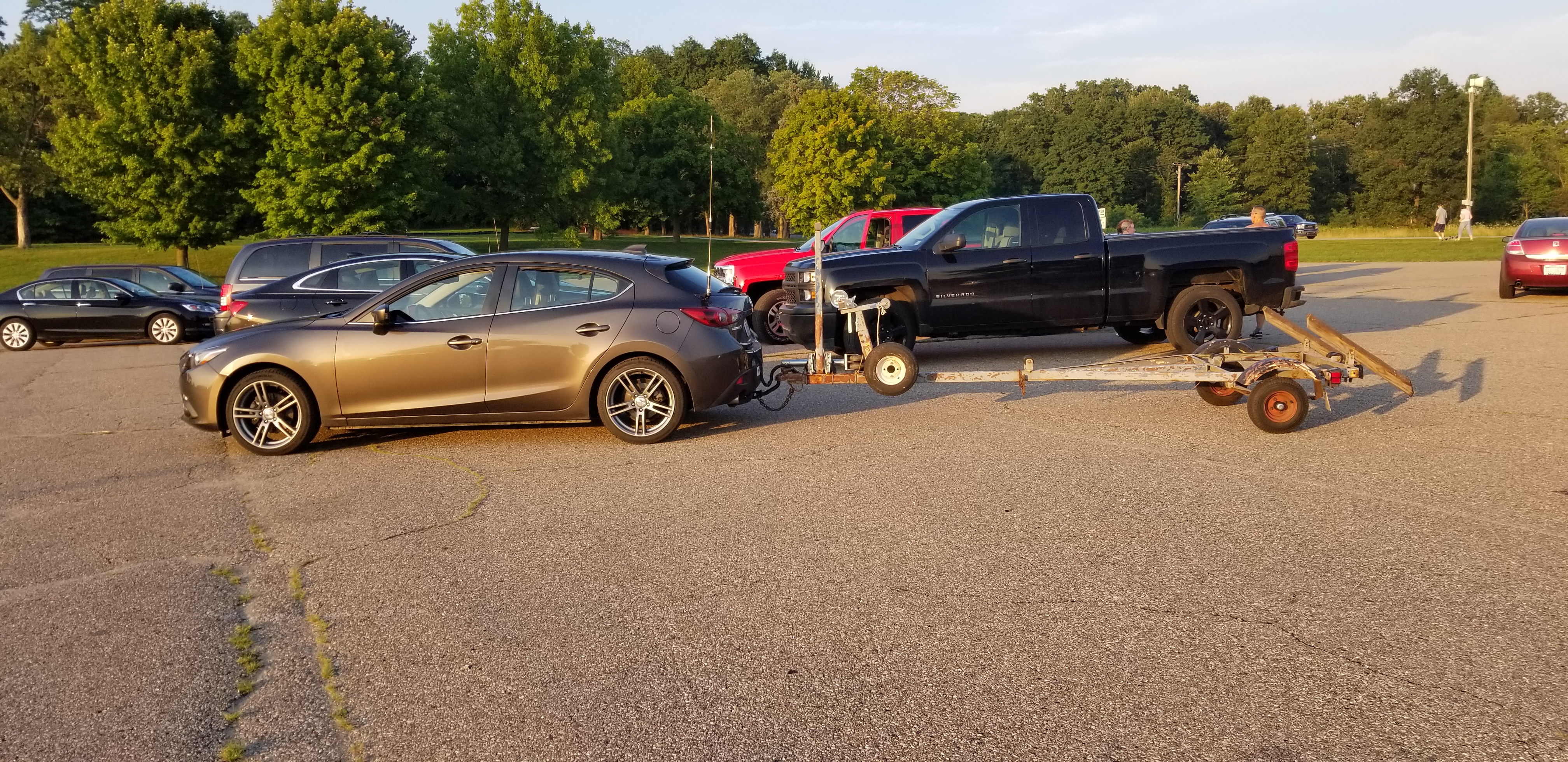
Matilda, with bonus appearance of the trailer for my boat, Aly Kat. Note the HV-7A antenna on a K400S mount on the hatch.
Matilda, with bonus appearance of the trailer for my boat, Aly Kat. Note the HV-7A antenna on a K400S mount on the hatch.

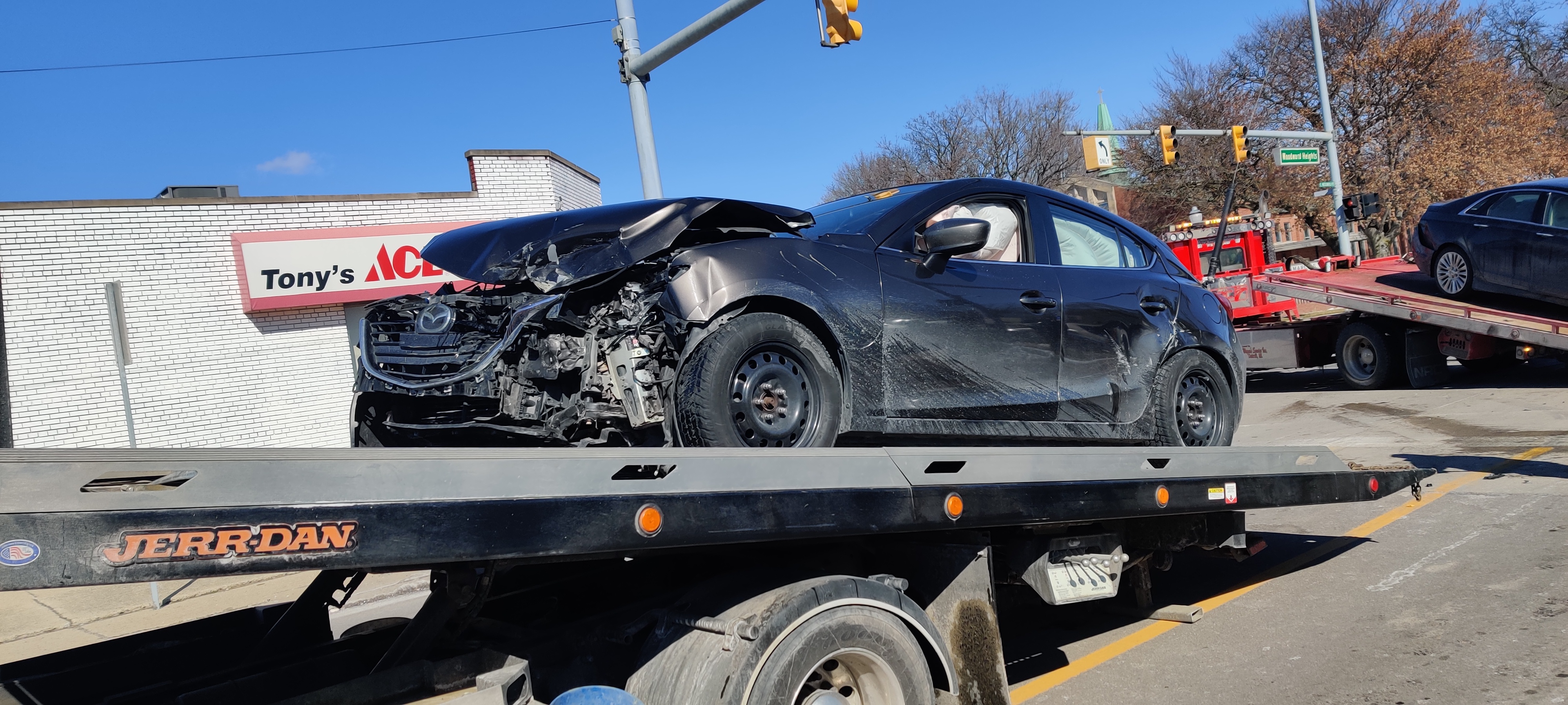
Matilda, on her final journey to Valhalla. Note the ATAS-120A on the same lip mount.

Matilda, on her final journey to Valhalla. Note the ATAS-120A on the same lip mount.

So I figured that, with my new car Minerva (a 2019 Mazda3 Sport hatch, with around 1200 miles), I would take the opportunity to ditch the mildly-inconvenient Diamond K400S hatch mount I was using for my Diamond HV-7A antenna (and recently my Yaesu ATAS-120A antenna), and put two brand-new Breedlove 195 SO239 ball mounts onto the car.
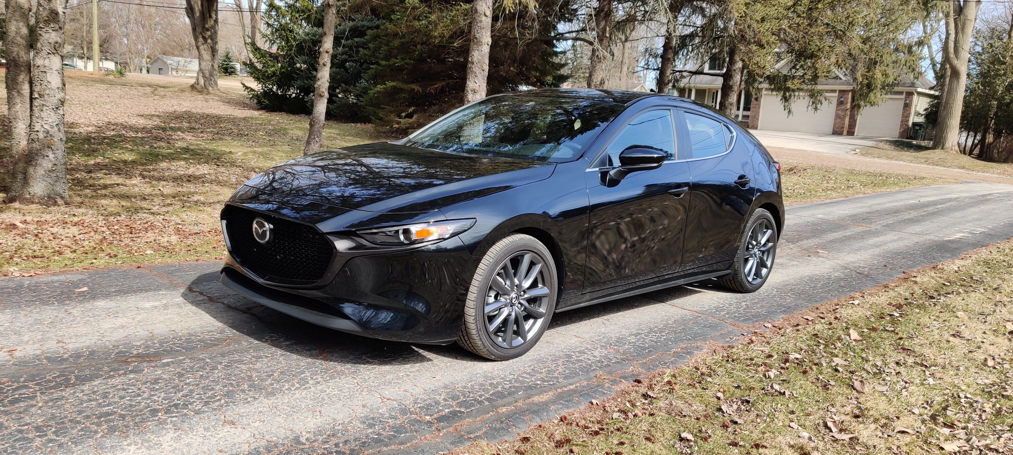
New car, Minerva. Note there are no antennae yet.

New car, Minerva. Note there are no antennae yet.

But of course I also like my cars to be clean and functional inside, so I needed to spend a lot more time than I did on Matilda with the radio install now that I have two mobile units. Also, I wanted big plates on the mounts so I did not can-opener the body steel…

Power

First and foremost, I needed a lot of power. The Yaesu FT-8900R daily rig draws up to 15A full-bore, and the Yaesu FT-857D all-band/all-modes rig draws 22A full-bore. In addition, I want to run my trailer light harness (LED lights on the car means I need a transistor box and a battery feed to run the trailer), and since Mazda for some unknown reason has something against accessory ports (seriously there is one gorramed port in the whole car), a 20A drop on PowerPole in the trunk is a good idea.

I had wired Matilda with some specialty AWG8 that was scrap from work, but I was not able to salvage much of that from her and plus I am under quarantine. However, I had a little left on the spool of AWG6 THHN from running a 50A 240VAC run to my garage. Score!
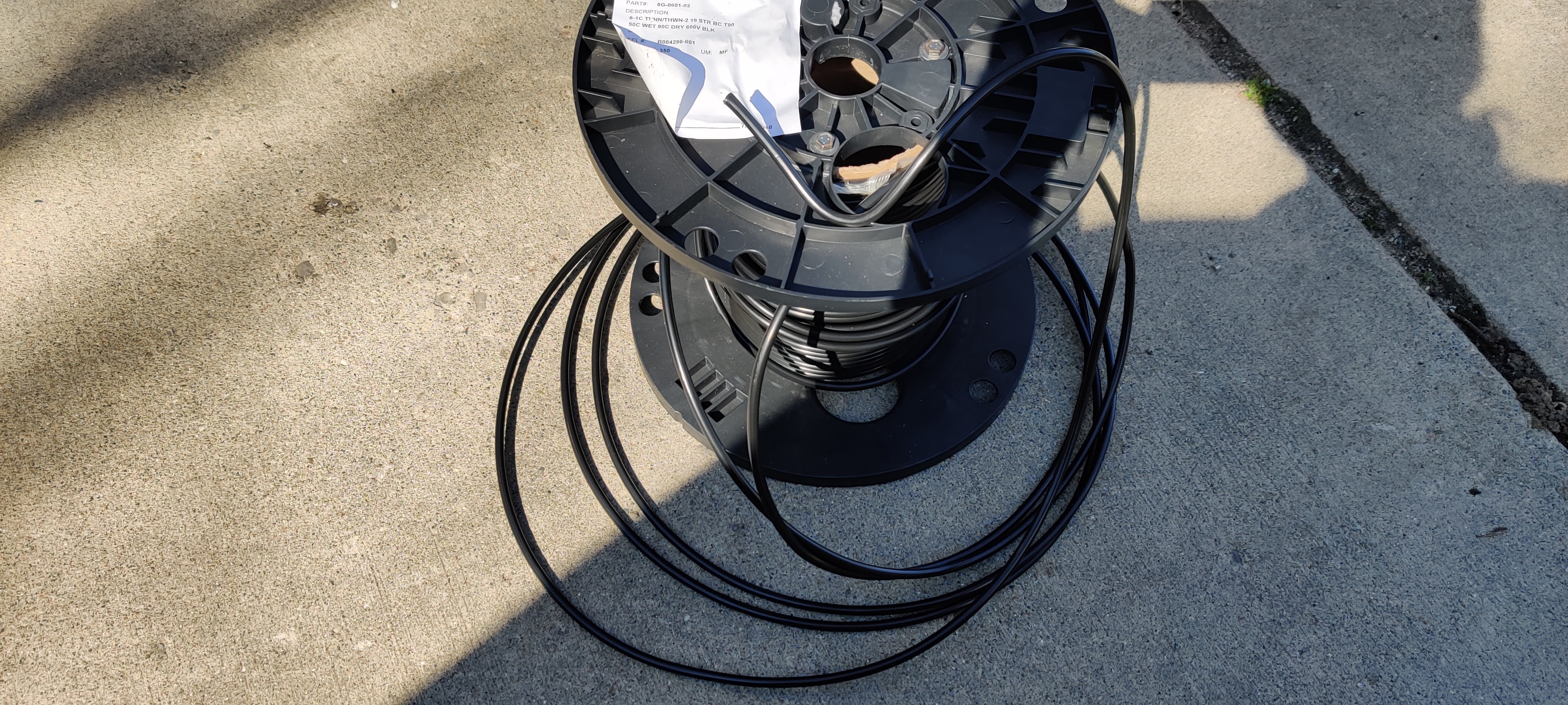
The remains of a spool of AWG6 THHN from Anixter, I used for a 50A 240VAC run to my garage.

The remains of a spool of AWG6 THHN from Anixter, I used for a 50A 240VAC run to my garage.

I bought some lugs and a crimper from Amazon to suit my sub-panel and the distribution block on the battery (Mazda is super helpful here!). The distribution block has several M6 studs with built-in high-current fuses. The panel and the wire are rated for around 80A in this use case, and conveniently there is an 80A fuse spare.
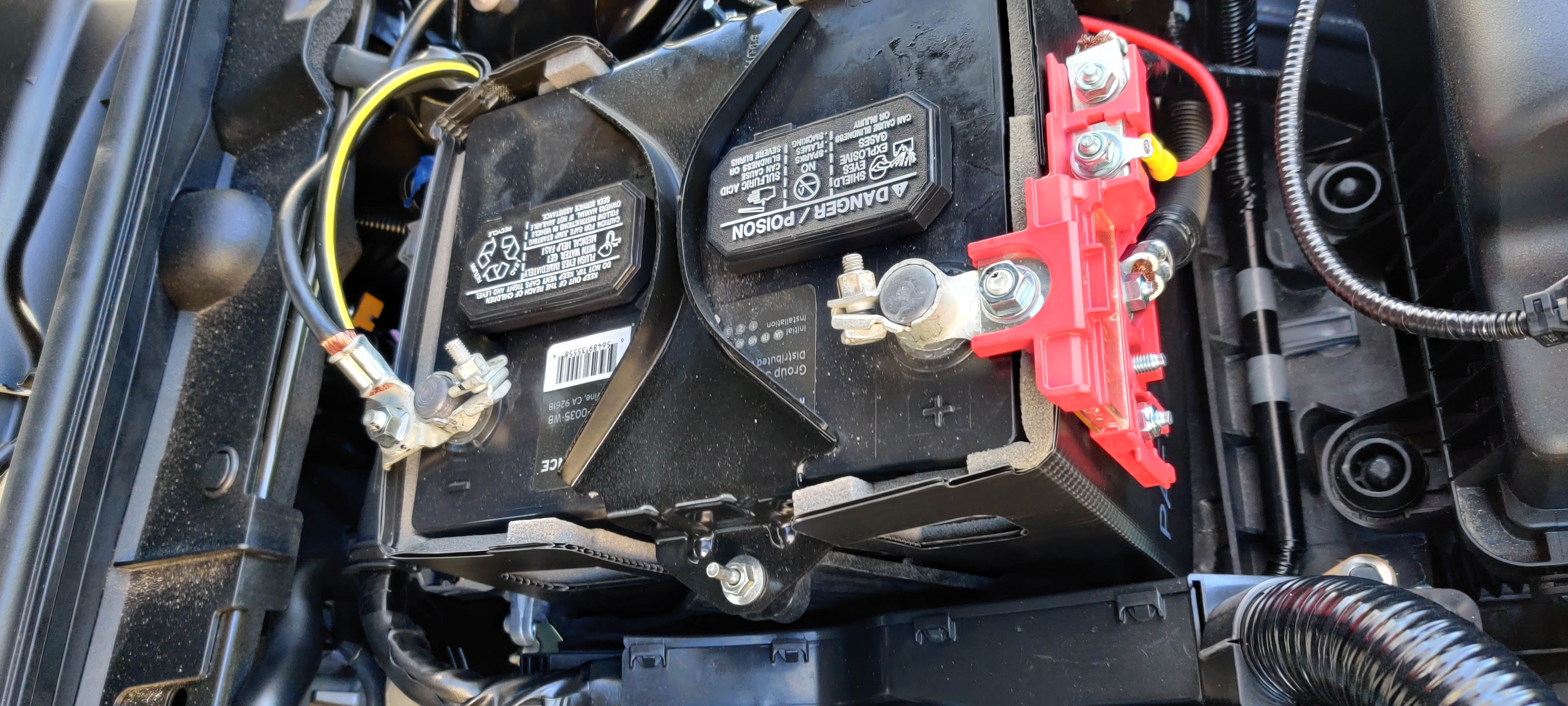
Battery with distribution block. The two bottom-most studs are both spare and fused at 80A.

Battery with distribution block. The two bottom-most studs are both spare and fused at 80A.

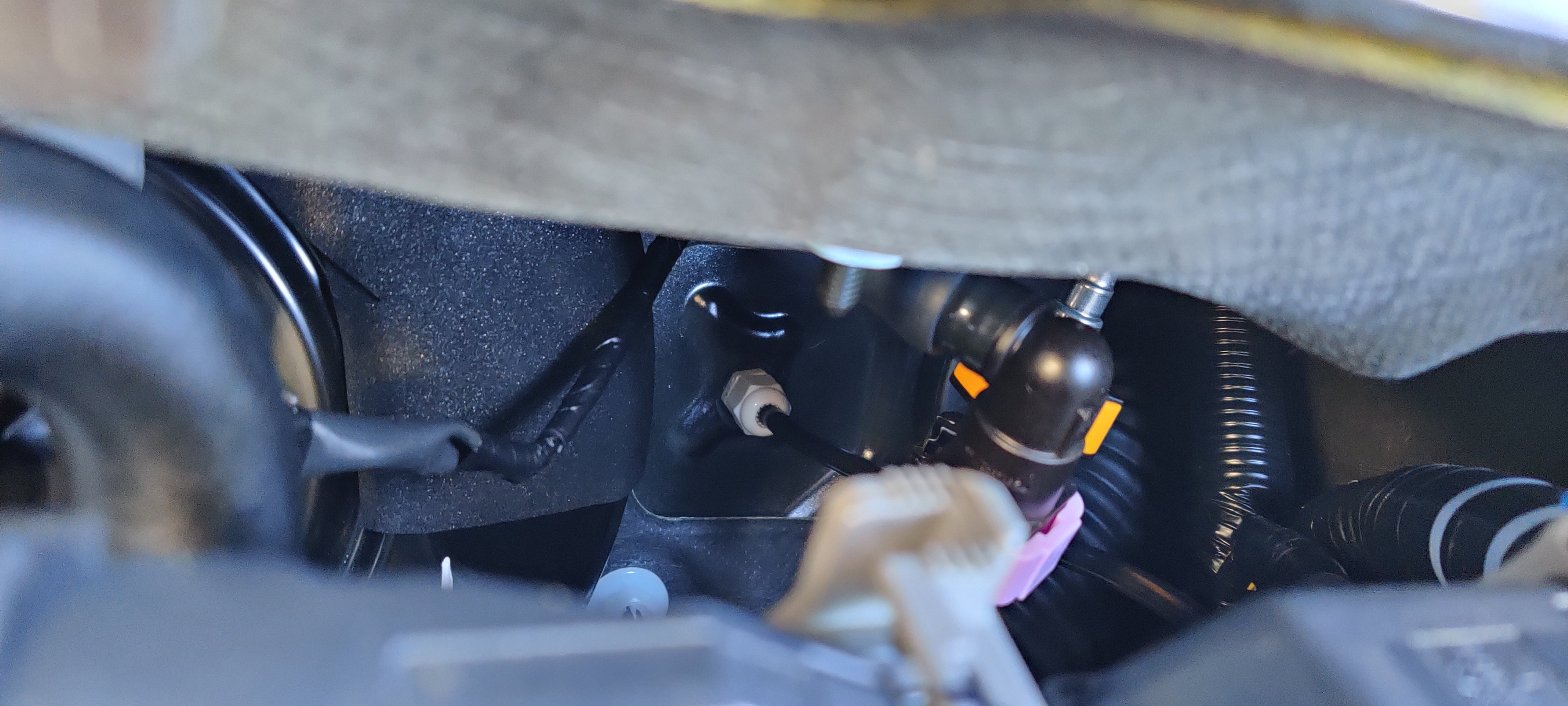
With any project like this, getting through the firewall in a safe, clean, and watertight way is a challenge. I used a gasketed cable gland through a conveniently blank spot. I say convenient…I did have to remove the air filter box, the battery, the ECM, the battery tray, and much of the ECM harness to access the area from the engine bay, and had to slice through the carpet and soundproofing mat in the cab. But it went well and now I have a watertight penetration.
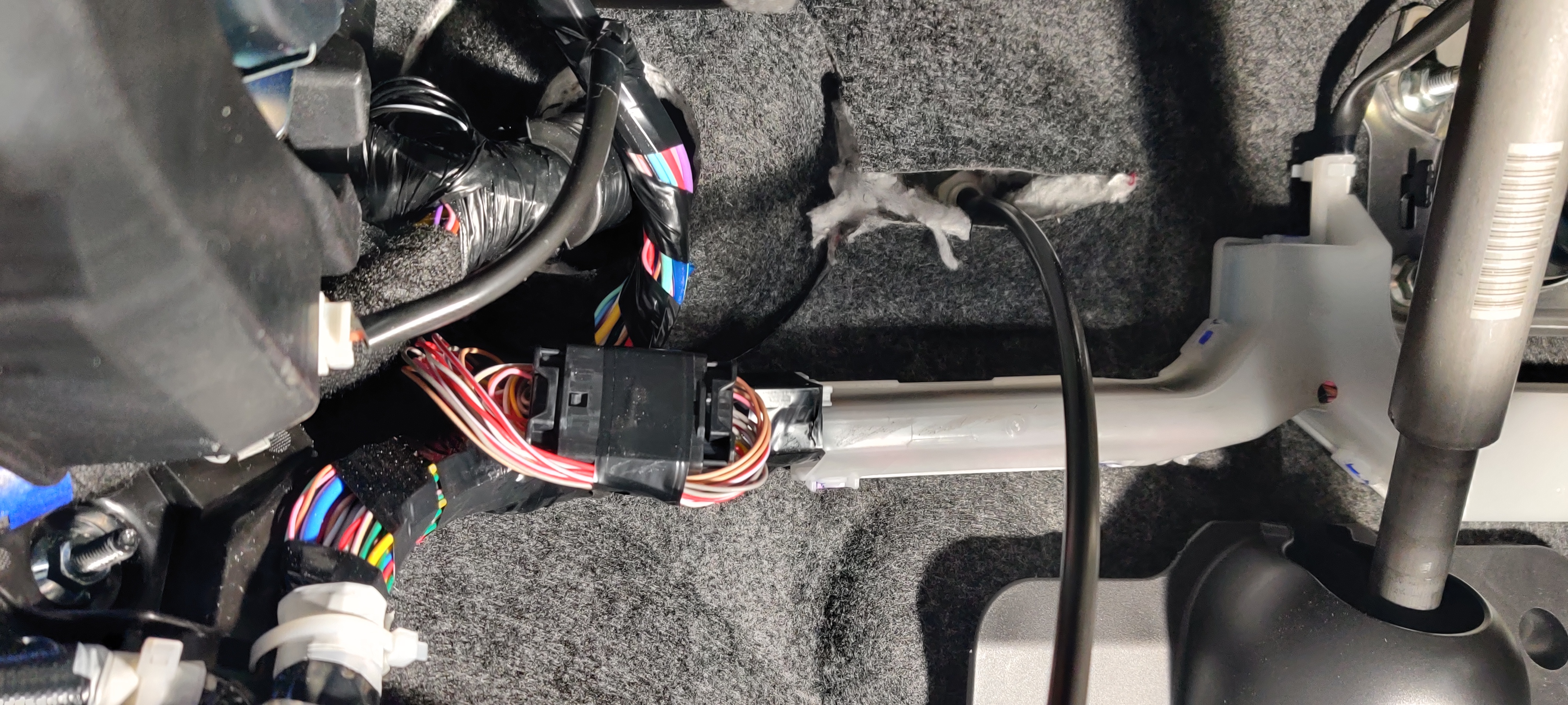
View of gland and cable inside cab. This is directly behind the instrument panel cluster.
View of gland and cable inside cab. This is directly behind the instrument panel cluster.

View of gland and cable in engine bay. This is directly behind the battery and ECM.

View of gland and cable in engine bay. This is directly behind the battery and ECM.

In the driver’s side rear quarterpanel, I lucked out. There is a wide-open area with a horizontal frame member forming a shelf, with plenty of space for my sub-panel and FT-8900R. I did have to relocate the “ELECTRICAL SUPPLY MODULE” off its bracket and forward, under the rear seatbelt reel, but I am confident this is OK.
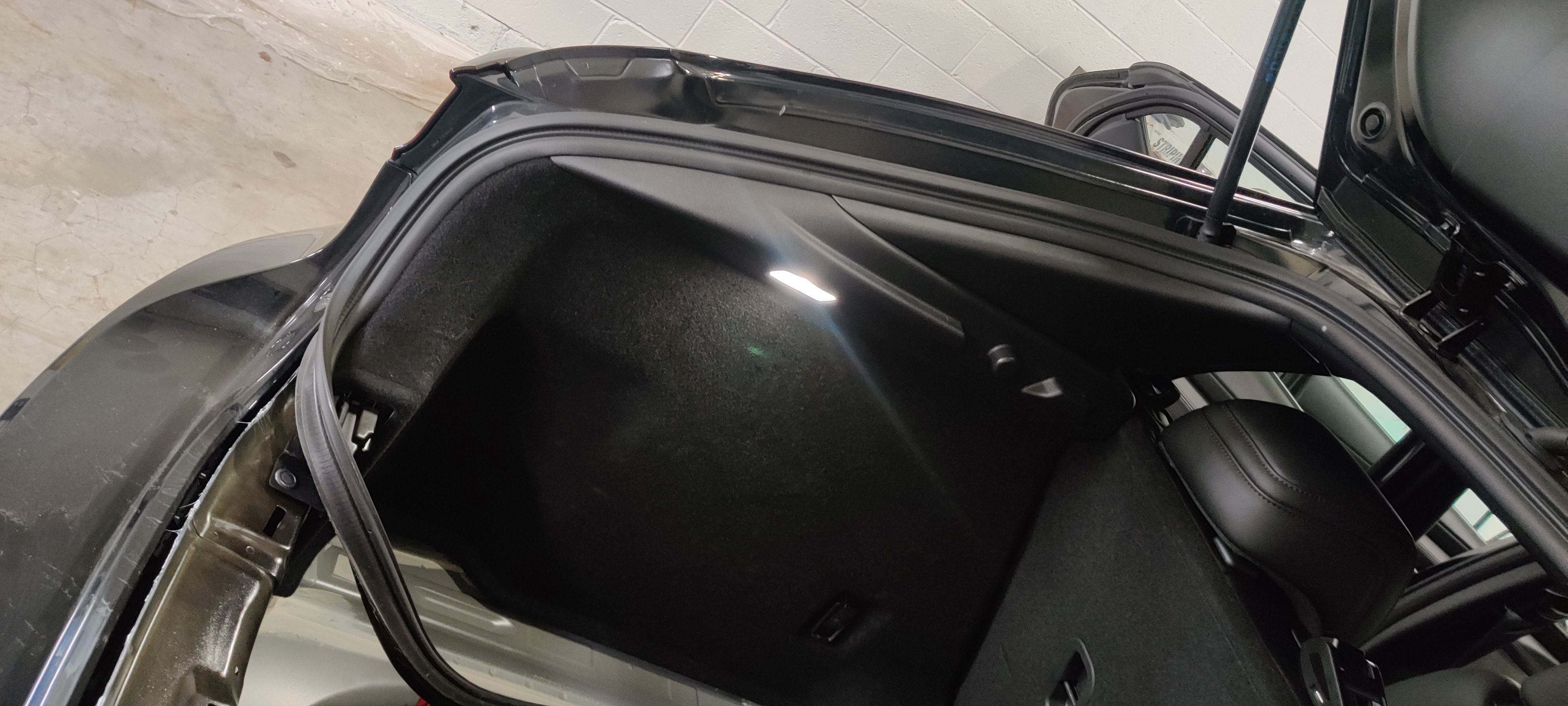
Driver's side of hatch, with the LED for the cargo area. Behind this carpet is an astonishingly large free space...and soon a subpanel and radio...

Driver’s side of hatch, with the LED for the cargo area. Behind this carpet is an astonishingly large free space…and soon a subpanel and radio…
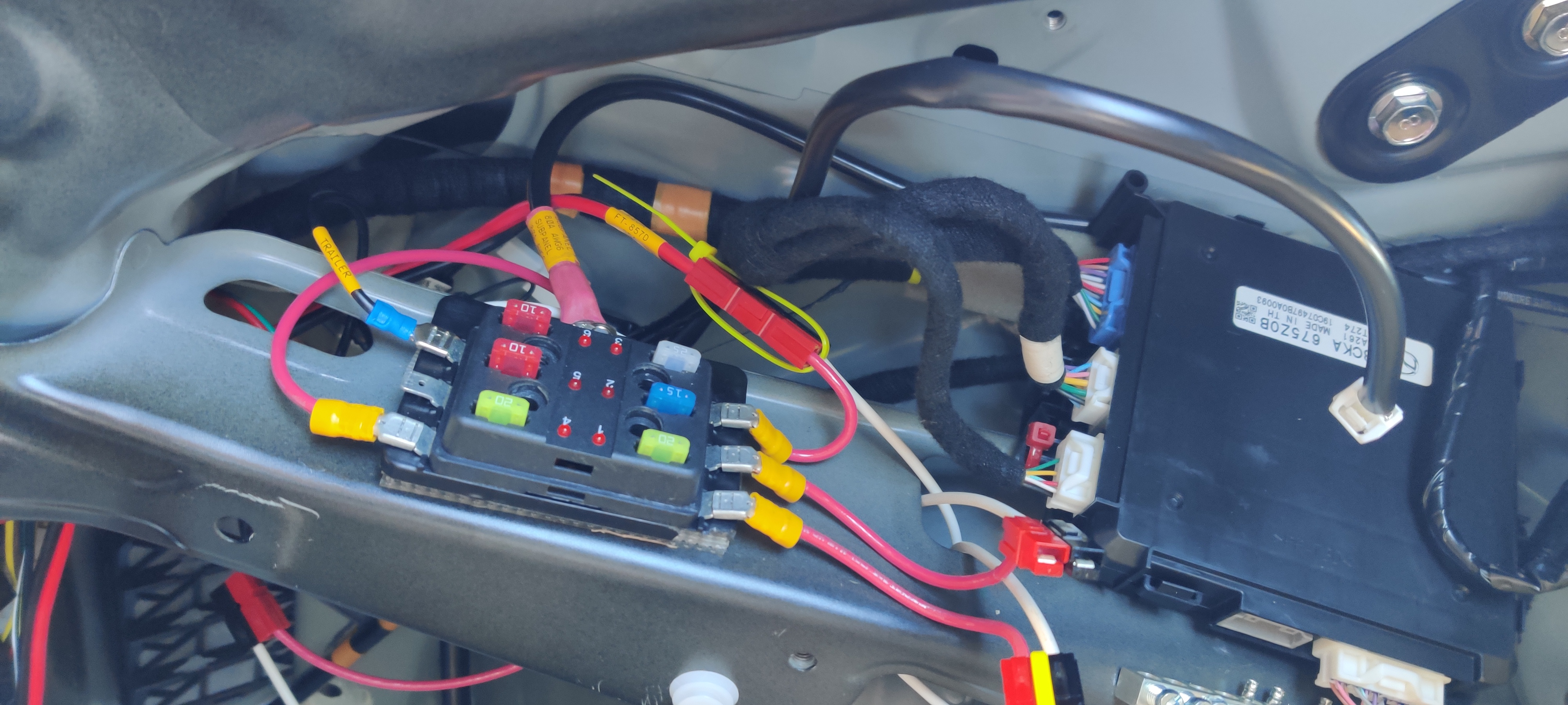
Driver's side rear quarterpanel. The right-most black box is the OEM "ELECTRICAL SUPPLY MODULE", relocated under the seatbelt reel. The subpanel is a cheap unit found at O'Reilly or similar.

Driver’s side rear quarterpanel. The right-most black box is the OEM “ELECTRICAL SUPPLY MODULE”, relocated under the seatbelt reel. The subpanel is a cheap unit found at O’Reilly or similar.

Once the engine bay was reassembled, the feed was labeled and landed on the stud.
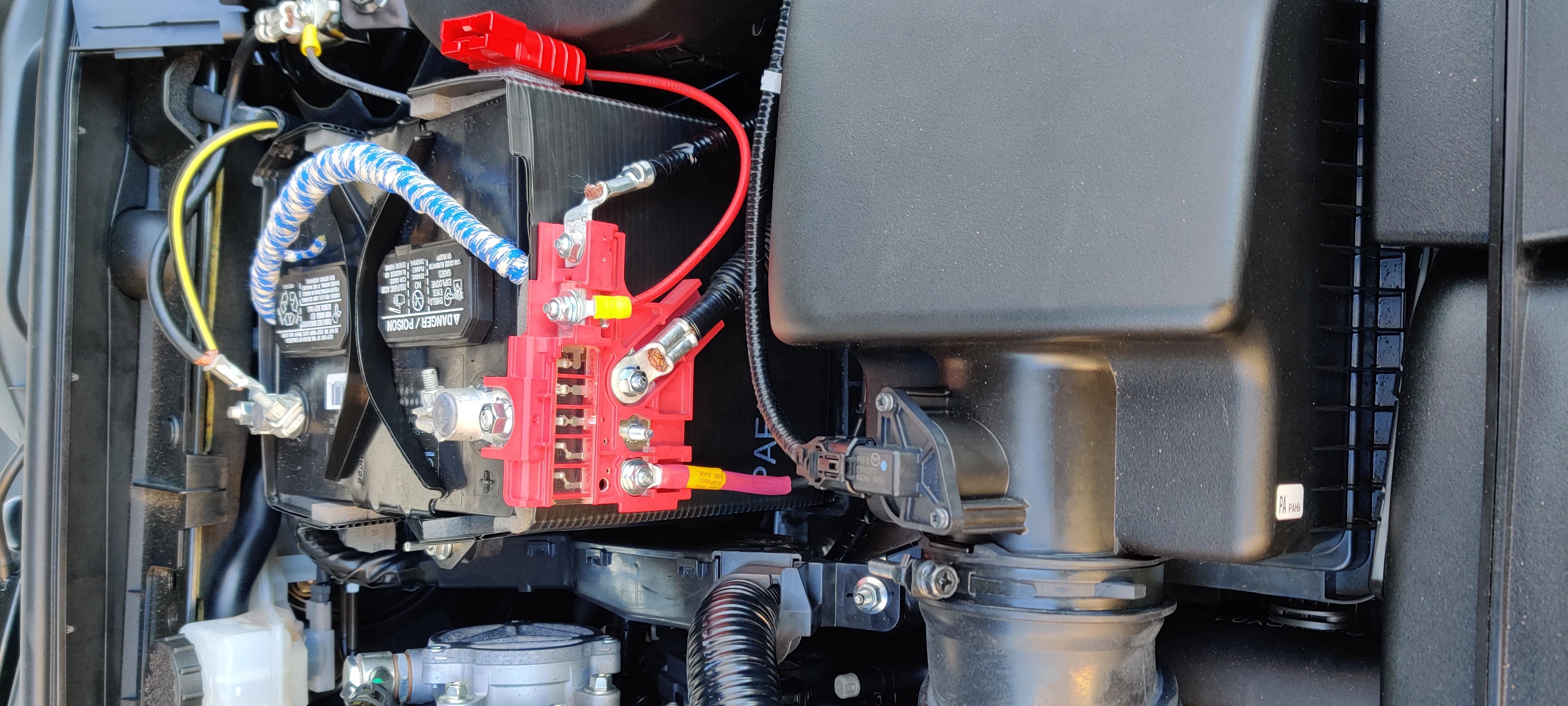
Engine bay, reassembled, with AWG6 feed to subpanel labeled and landed on 80A stud.

Engine bay, reassembled, with AWG6 feed to subpanel labeled and landed on 80A stud.

FT-8900R Installation

Now that I had power, I wanted to install my FT-8900R. This is an FM-only quad-band (70cm, 2m, 6m, 10m) dual-VFO/dual-receiver radio that is excellent at repeater work in the local area, matched with the HV-7A antenna.

The FT-8900R is a ridiculously compact radio, and gets even smaller with the head detached on the separation kit. With the mobile mounting bracket, the whole radio fits flush behind the carpeting on the diagonal frame rail over the shelf. Three #8×1/2″ sheet metal screws hold the bracket in place.
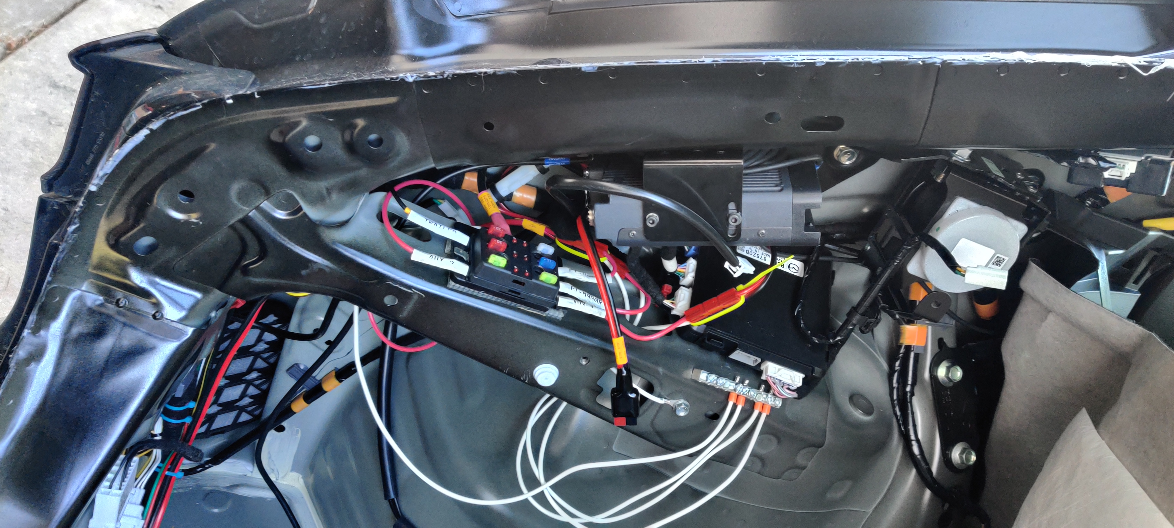
FT-8900R mounted on diagonal frame rail over shelf and subpanel. White flying connector is for cargo area LED; flying PowerPole is 20A auxiliary for cargo area. Ziptied PowerPole over OEM module is feed for FT-857D on the other side of the car; the one under the FT-8900R is for that radio.

FT-8900R mounted on diagonal frame rail over shelf and subpanel. White flying connector is for cargo area LED; flying PowerPole is 20A auxiliary for cargo area. Ziptied PowerPole over OEM module is feed for FT-857D on the other side of the car; the one under the FT-8900R is for that radio.

I eyeballed the placement of the Breedlove mount so the ball was centered between the fuel door and the combo light, then marked out the holes. Pucker factor 100% drilling holes in brand-new body panels. A quick deburr inside and out, and it was time to pull the panels together…whereupon I had an issue. The inside frame members were too close to the outside panels for me to reach the holes. Fortunately, I also really like rope (get your minds out of the gutter; I am a sailor and taught Pioneering merit badge for years through my BSA career). I threaded some light line through the holes and grabbed it inside the car, then tied it through the backing plate with a slipknot. Careful feeding of plate and knot into the interstitial space and I could pull the whole plate flush and aligned with the outer holes.
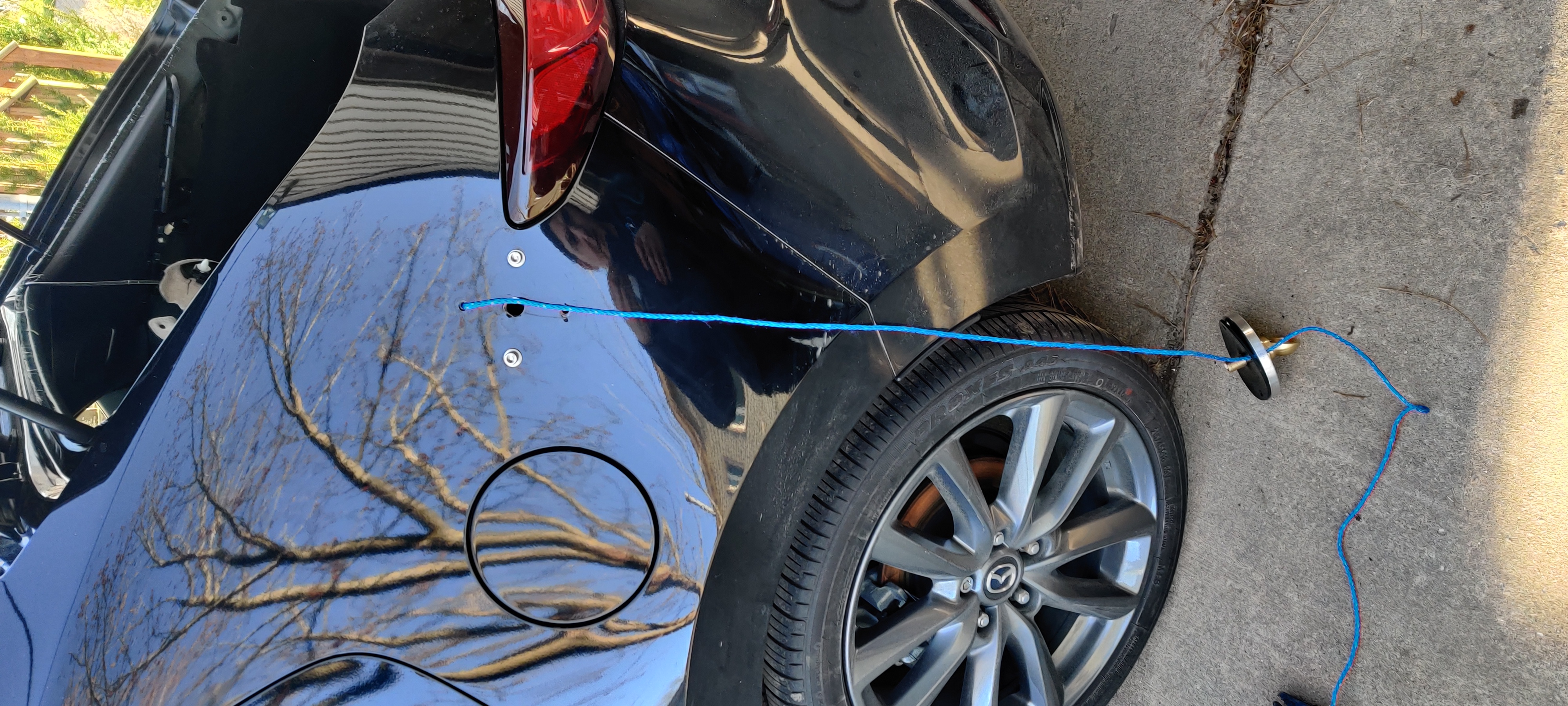
A clever fishing expedition, pulling the backing plate of the Breedlove mount against the inside of the body panel so I can get the two plates aligned with each other and the body panel.
A clever fishing expedition, pulling the backing plate of the Breedlove mount against the inside of the body panel so I can get the two plates aligned with each other and the body panel.

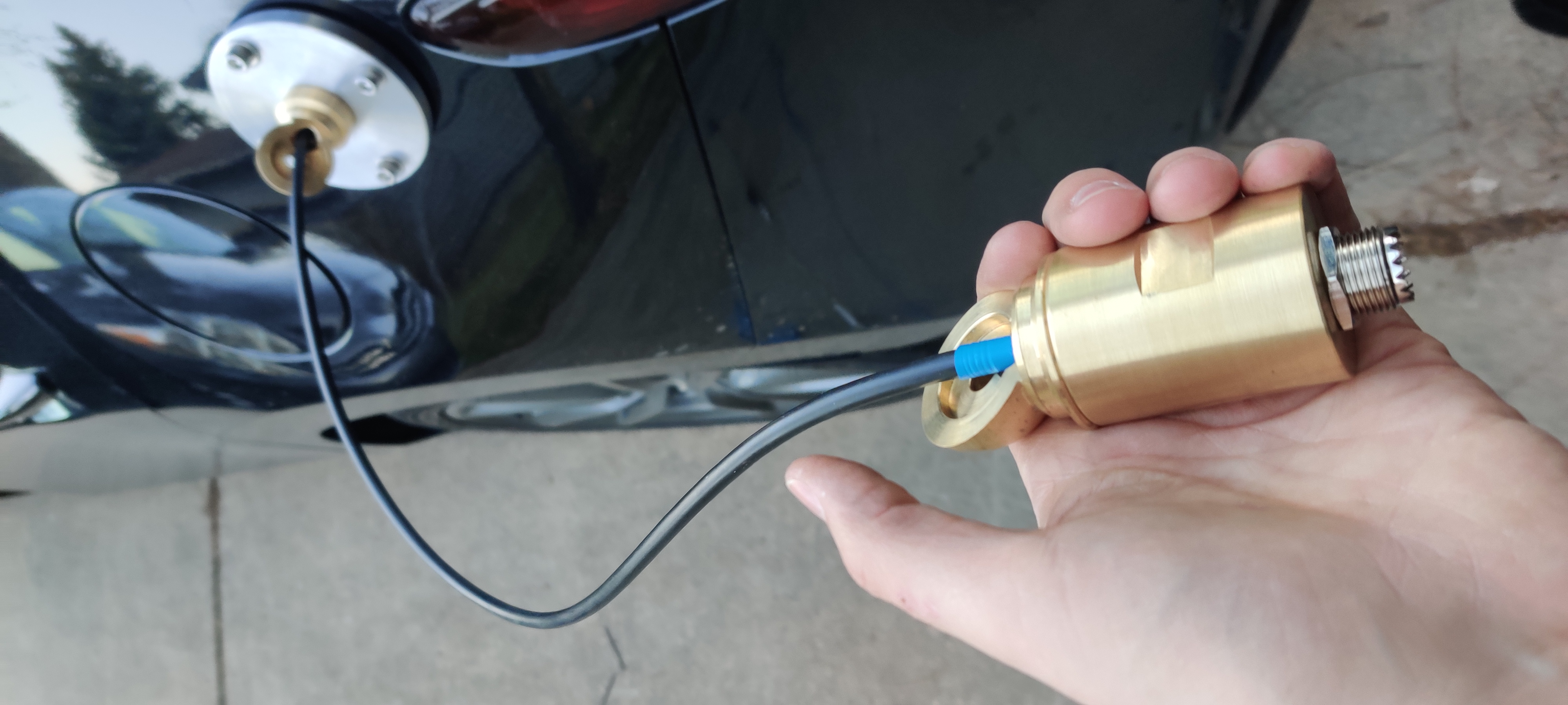
Fishing the LMR-240 through the ball and inner shaft, into the cargo area.
Fishing the LMR-240 through the ball and inner shaft, into the cargo area.

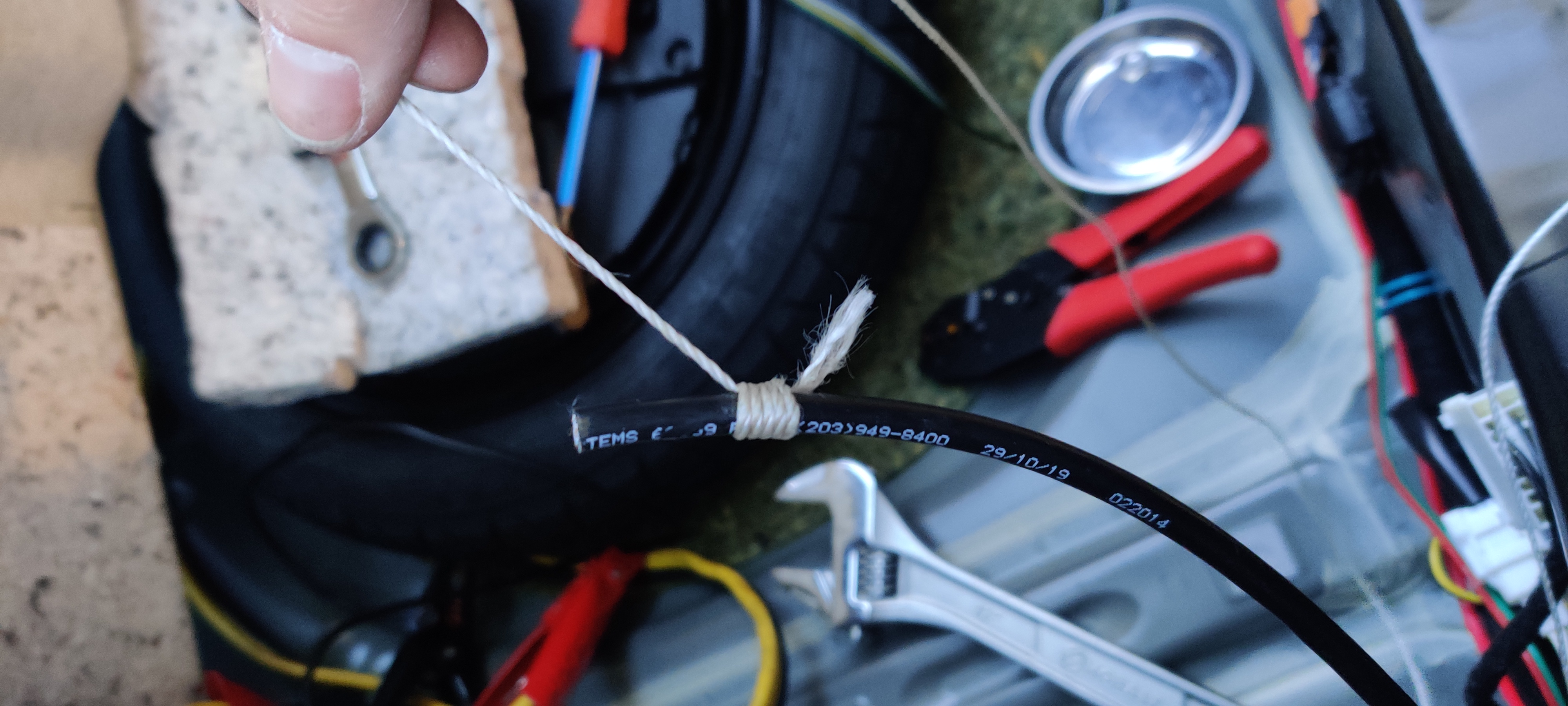
All that time in the Scouts really paid off; a traditional whipping bites well enough on the coax to act as a non-damaging pull.
All that time in the Scouts really paid off; a traditional whipping bites well enough on the coax to act as a non-damaging pull.

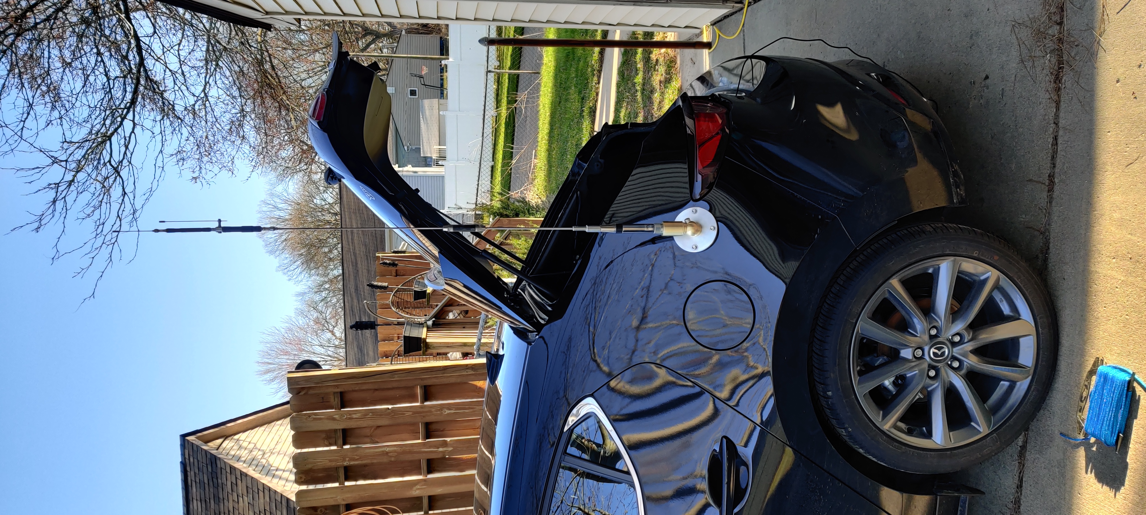
Completed mount with HV-7A standing proud and plumb.
Completed mount with HV-7A standing proud and plumb.

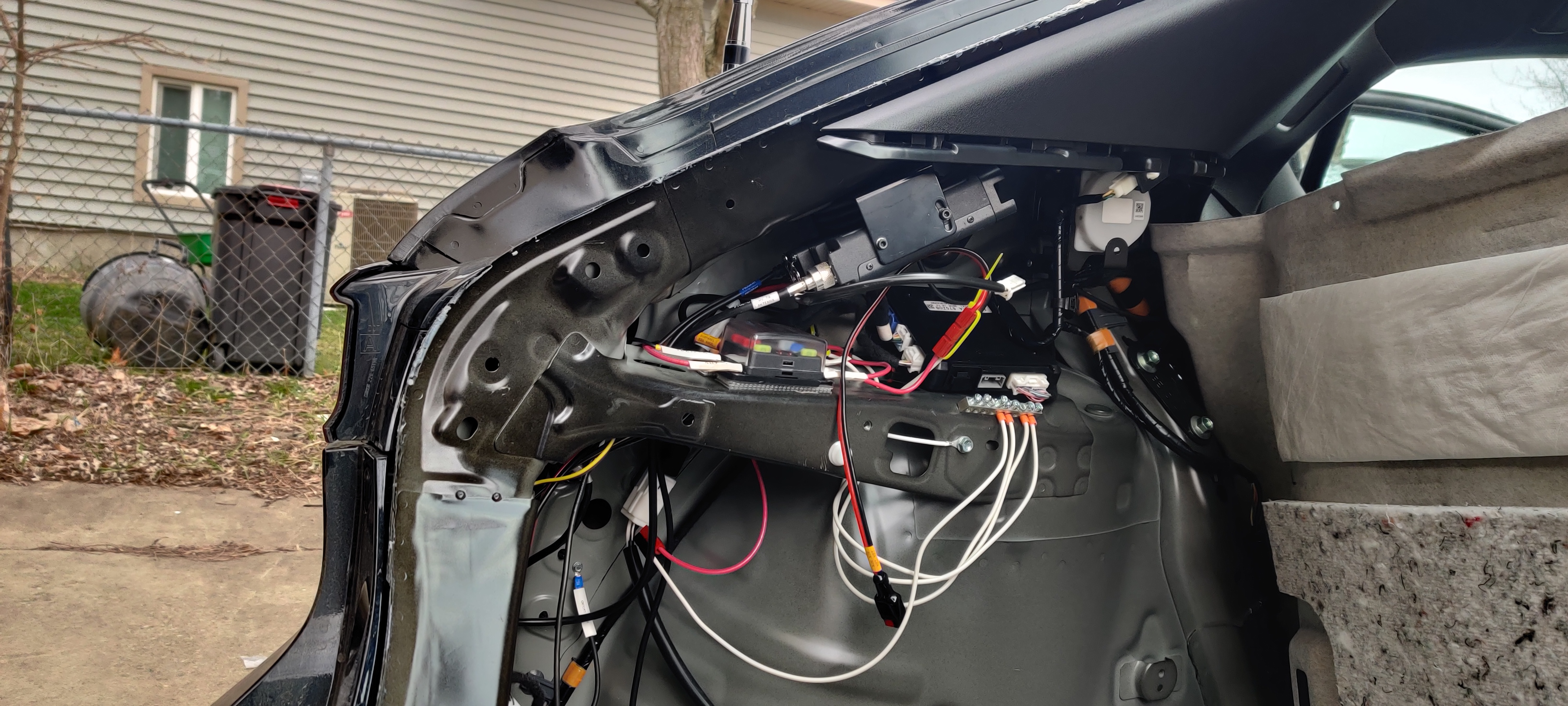
Completed installation, with coax labeled and terminated. The  backing plate for the mount is approximately behind the triangular gap formed by the FT-8900R and the OEM module. All access was through a narrow slit aft of the inner frame member, shown with a large knockout and the Breedlove grounding wire.

Completed installation, with coax labeled and terminated. The backing plate for the mount is approximately behind the triangular gap formed by the FT-8900R and the OEM module. All access was through a narrow slit aft of the inner frame member, shown with a large knockout and the Breedlove grounding wire.

With everything installed and confirmed working, I ran the separation cable into the passenger area, a programming cable extension into the cargo area, and an external speaker cable into the cargo area, and buttoned everything up.
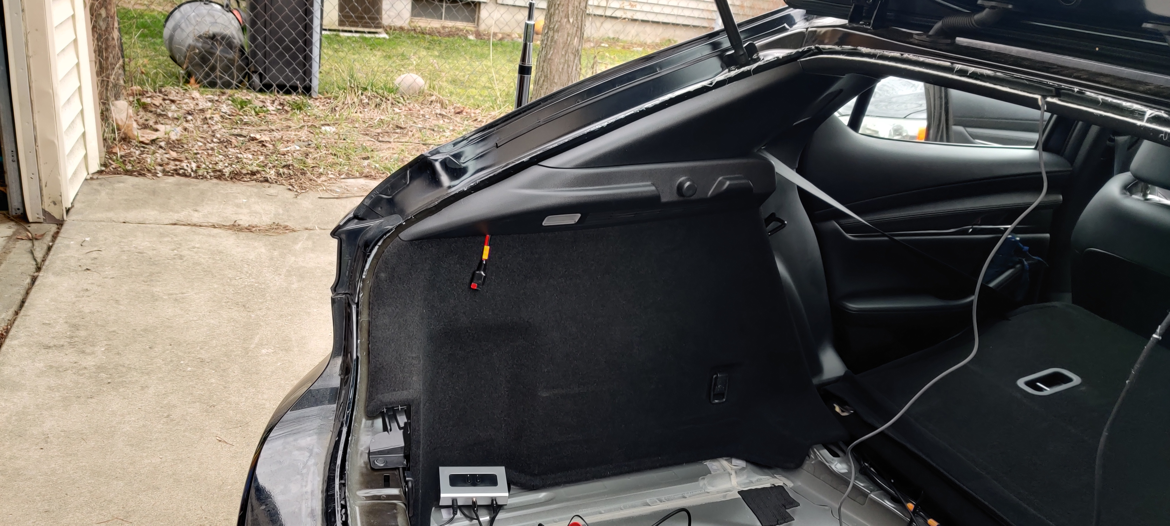
Driver's side rear quarterpanel, now with radio and subpanel installed. Note the 20A PowerPole drop tucked under the cargo area LED, and the 1-2 switch for external speaker (soon to be replaced with an actual mixer). Not shown (because framing!) programming cable extension.

Driver’s side rear quarterpanel, now with radio and subpanel installed. Note the 20A PowerPole drop tucked under the cargo area LED, and the 1-2 switch for external speaker (soon to be replaced with an actual mixer). Not shown (because framing!) programming cable extension.

FT-857D

Next up, the FT-857D. This is an all-band (something like 1MHz through 700MHz) all-mode (AM, FM, upper sideband, lower sideband, packet and digital modes) dual-VFO/single-receiver radio that is excellent at longer-range things and packet digital work, matched with the motorized tunable ATAS-120A antenna.

The FT-857D is nowhere near as compact as the FT-8900R, even with the separation kit. With the mobile mounting bracket, the radio does bow out the carpeting when mounted horizontally on the shelf inside the passenger side rear quarterpanel. Two #8-32 bolts and Nylock nuts hold the bracket in place.
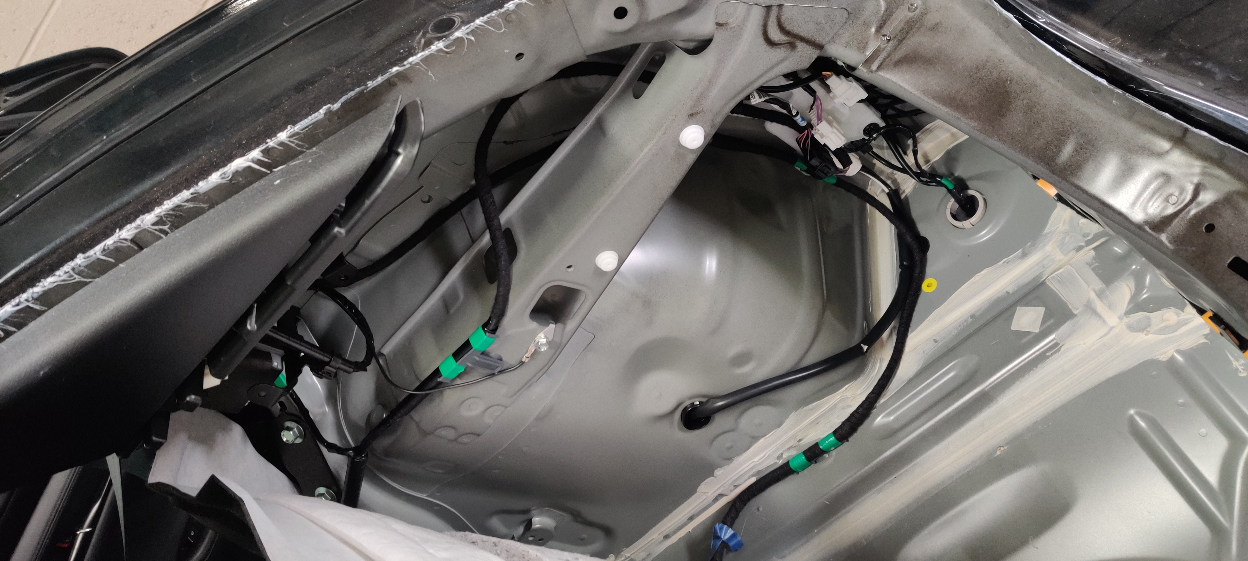
Passenger side rear quarterpanel has a similar shelf arrangement as the driver's side, but no OEM module to deal with.

Passenger side rear quarterpanel has a similar shelf arrangement as the driver’s side, but no OEM module to deal with.
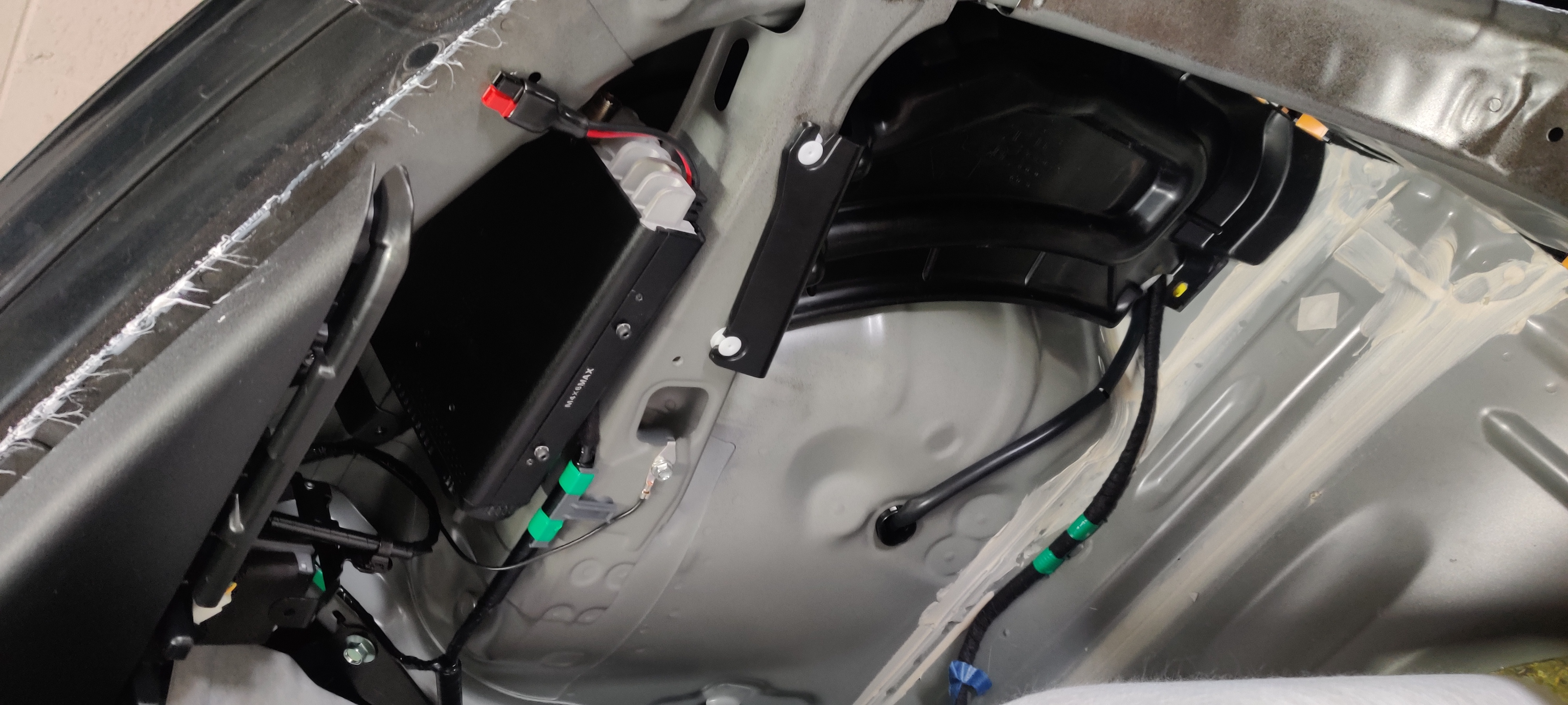
FT-857D mounted, with bonus appearance of soundproofing plug for interstitial space.

FT-857D mounted, with bonus appearance of soundproofing plug for interstitial space.

Mounting the antenna was much the same as for the FT-8900R, but I actually measured the mount position so it matched.
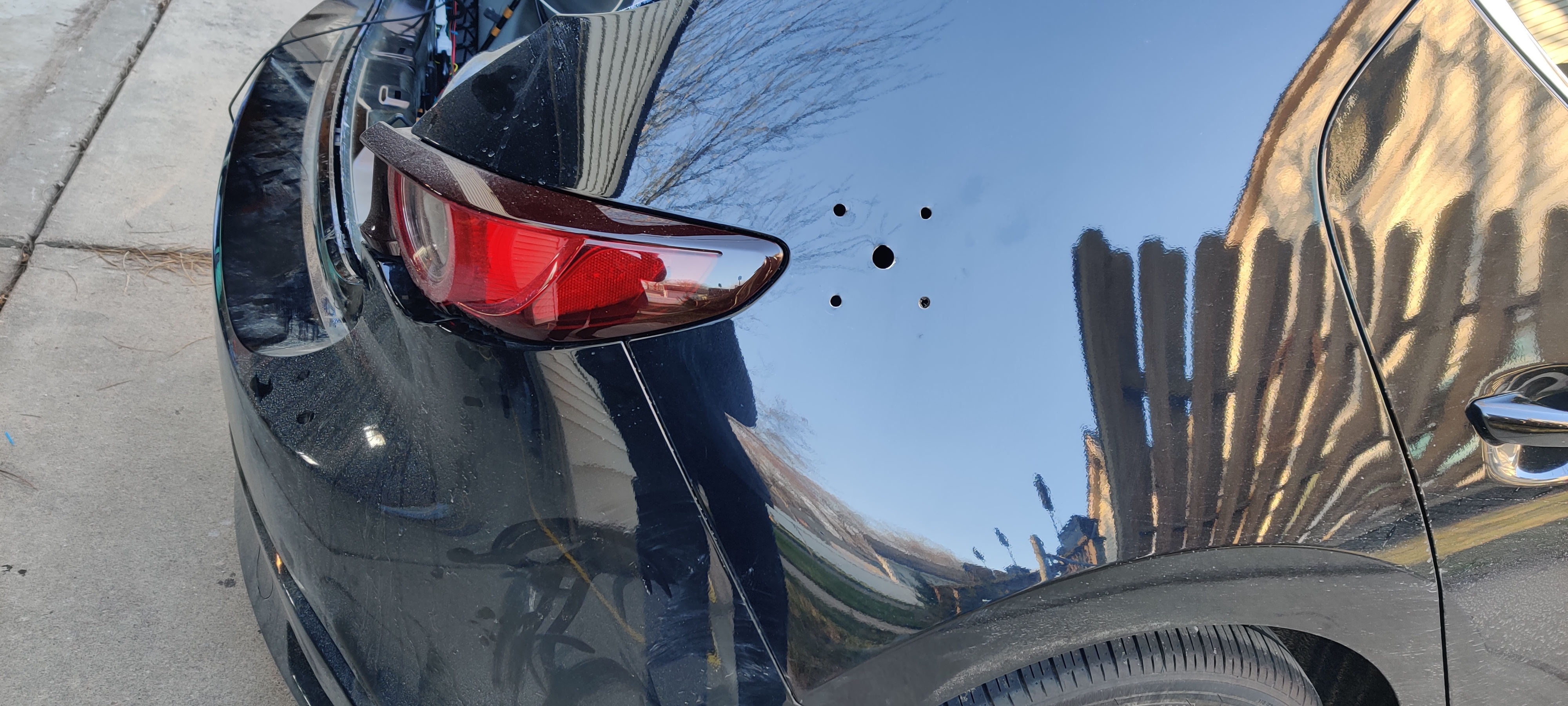
Five mounting holes for the Breedlove mount. The central one is 5/8" and accepts the brass inner shaft for the cable; the outer ones are 11/32" for the mounting bolts.

Five mounting holes for the Breedlove mount. The central one is 5/8″ and accepts the brass inner shaft for the cable; the outer ones are 11/32″ for the mounting bolts.
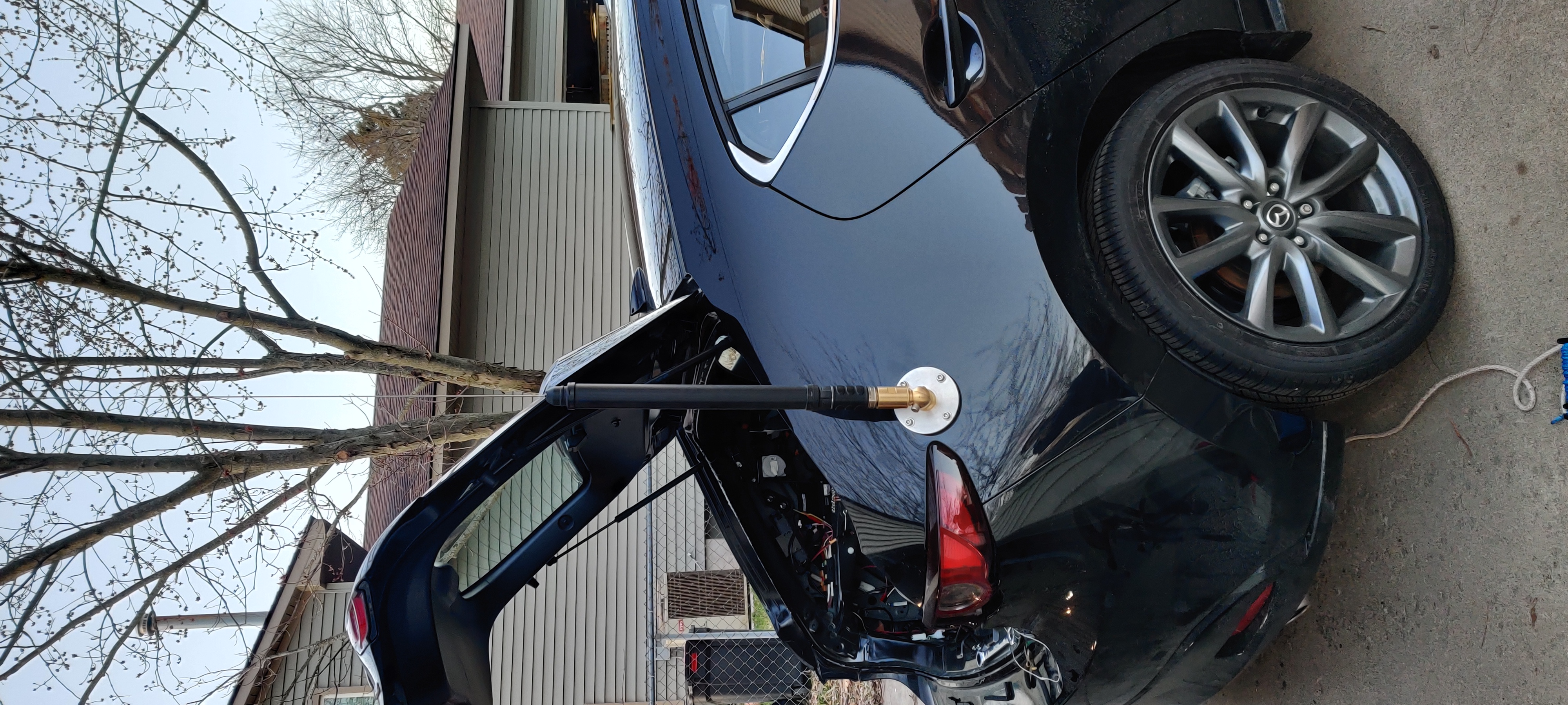
ATAS-120A mounted proud and plumb

ATAS-120A mounted proud and plumb

When everything was tested, I could not get any reception on KEC63 (this station broadcasts from the National Weather Service in White Lake on a frequency of 165.55MHz...). Which, you know, bad.

So I cut the connector off and redid it. Everything good the second round; I think I got some of the braid into the center conductor the first time around.
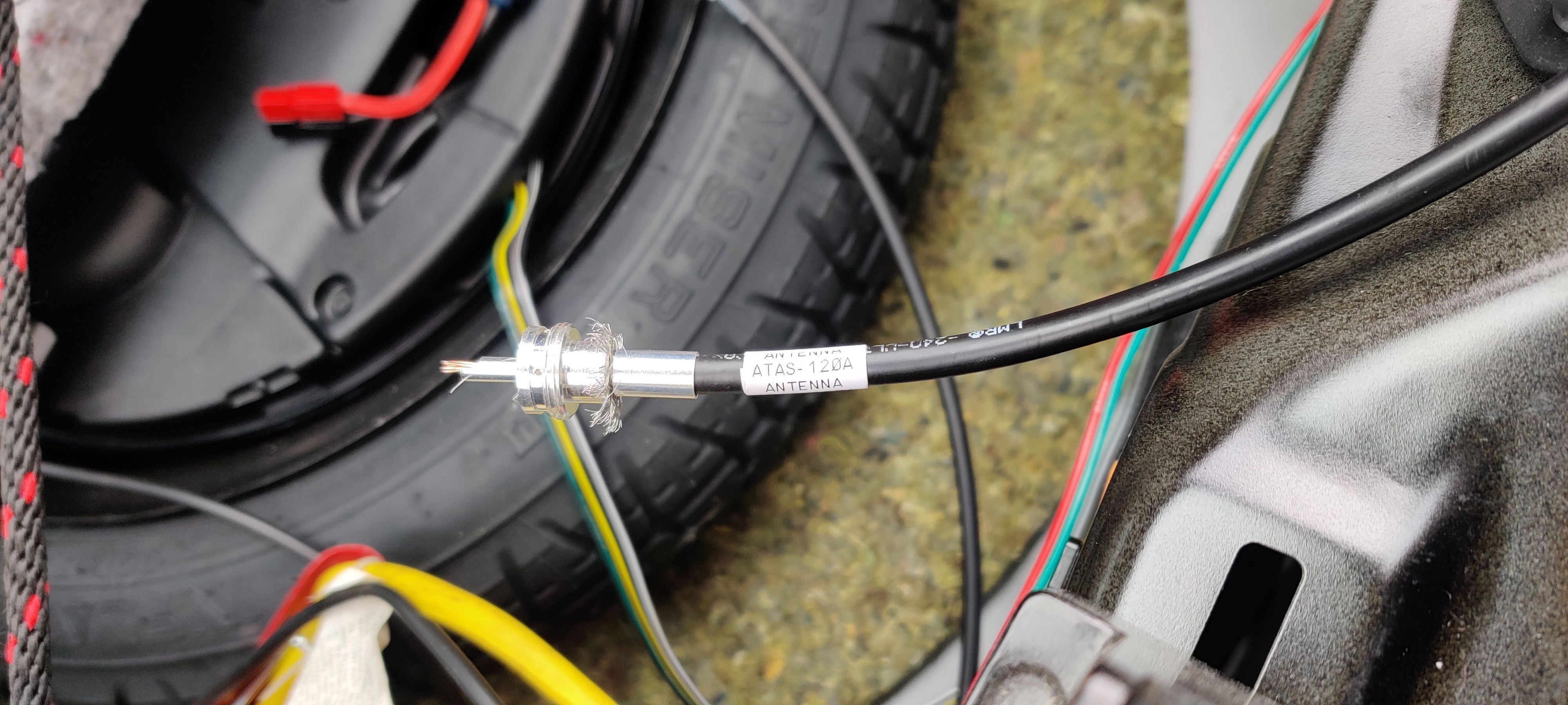
In-process round two of PL-259 connector for the ATAS-120A.
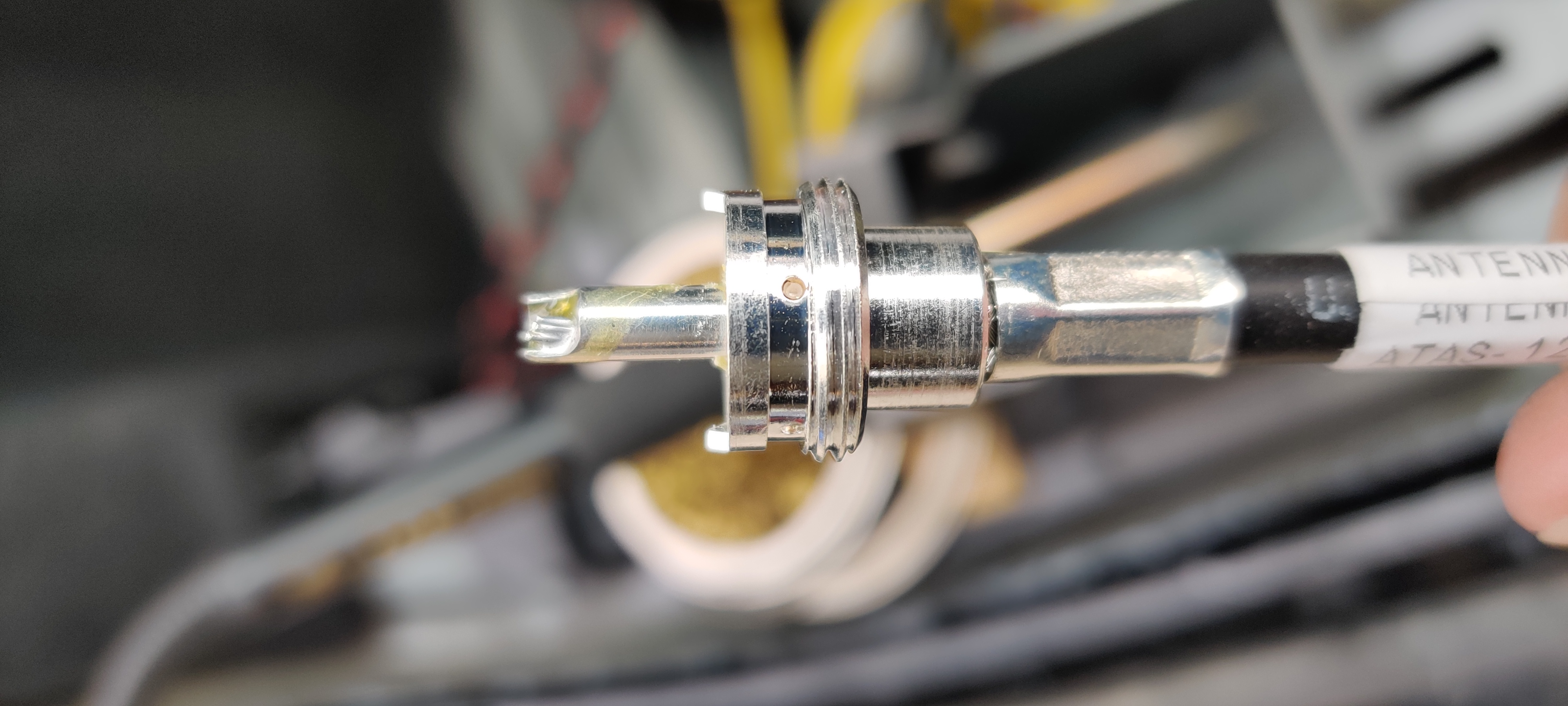
In-process round two of PL-259 connector for the ATAS-120A.

Completed (and working!) PL-259 connector.

Completed (and working!) PL-259 connector.

Once everything tested out OK I mounted the CF-706 duplexer, ran the separation cables into the passenger area and an external speaker cable into the cargo area, and buttoned everything up. (No programming cable extension yet; it is in the mail still, along with a Bluetooth adapter from KC8UFV).
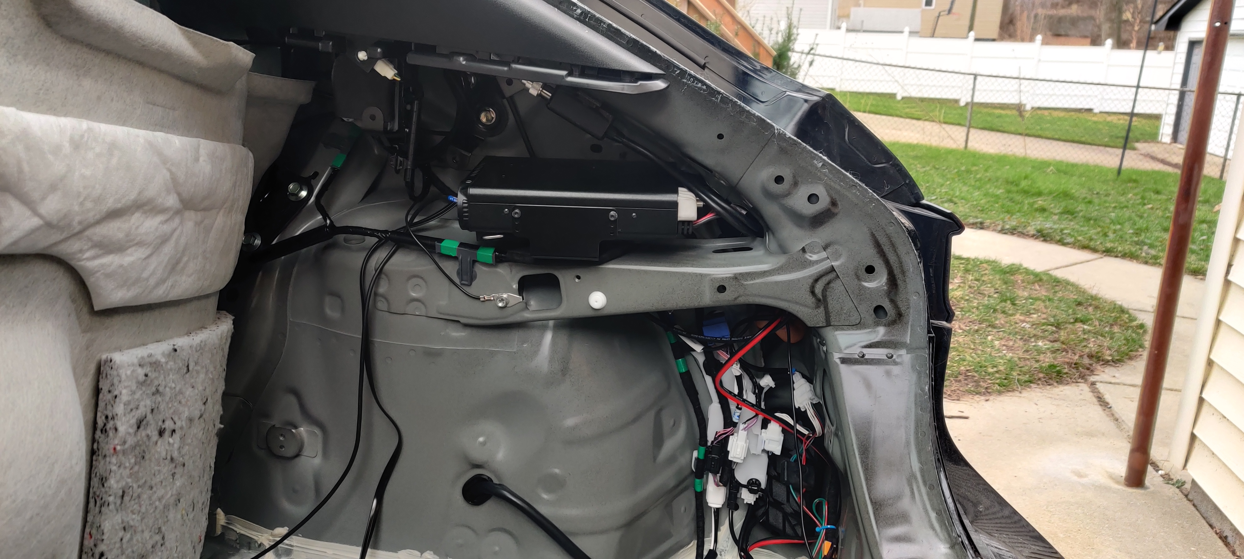
Completed installation. Note how little space behind the radio there is for cabling. Also note the CF-706 duplexer mounted above the radio on the diagonal frame rail.
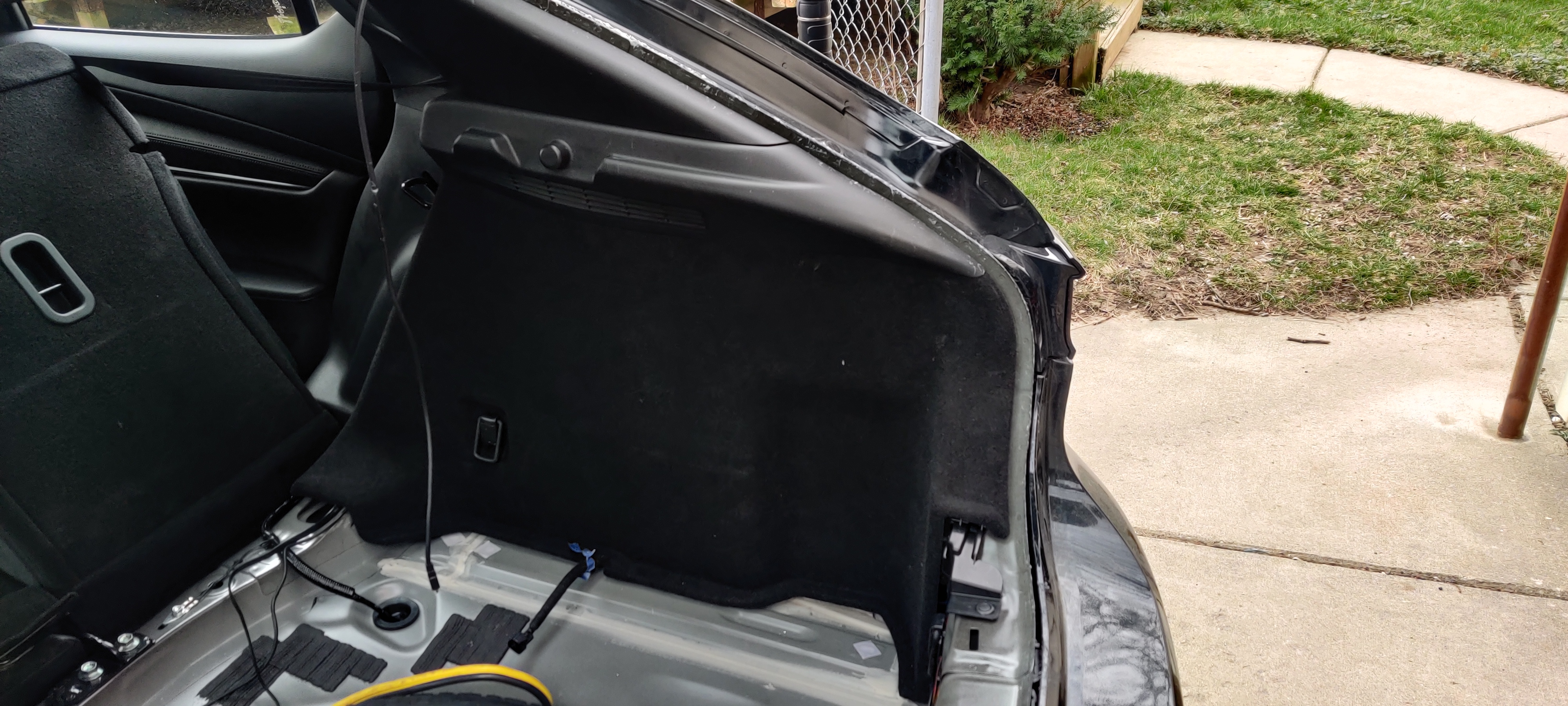
Completed installation. Note how little space behind the radio there is for cabling. Also note the CF-706 duplexer mounted above the radio on the diagonal frame rail.

Just the barest hint of a curve in the vent panel over the FT-857D. Otherwise, buttoned up just fine.

Just the barest hint of a curve in the vent panel over the FT-857D. Otherwise, buttoned up just fine.

Interfaces

Inside the passenger area, it was time to figure out where the heck I was going to put two microphones and two heads. In Matilda, I had the FT-8900R head mounted under the dashboard near the door knee panel, and that worked well. It fit right over the hood release lever and below the random little storage compartment Mazda bequeathed the 2019 with.
FT-8900R head shown under dashboard, just above the hood release lever.

FT-8900R head shown under dashboard, just above the hood release lever.

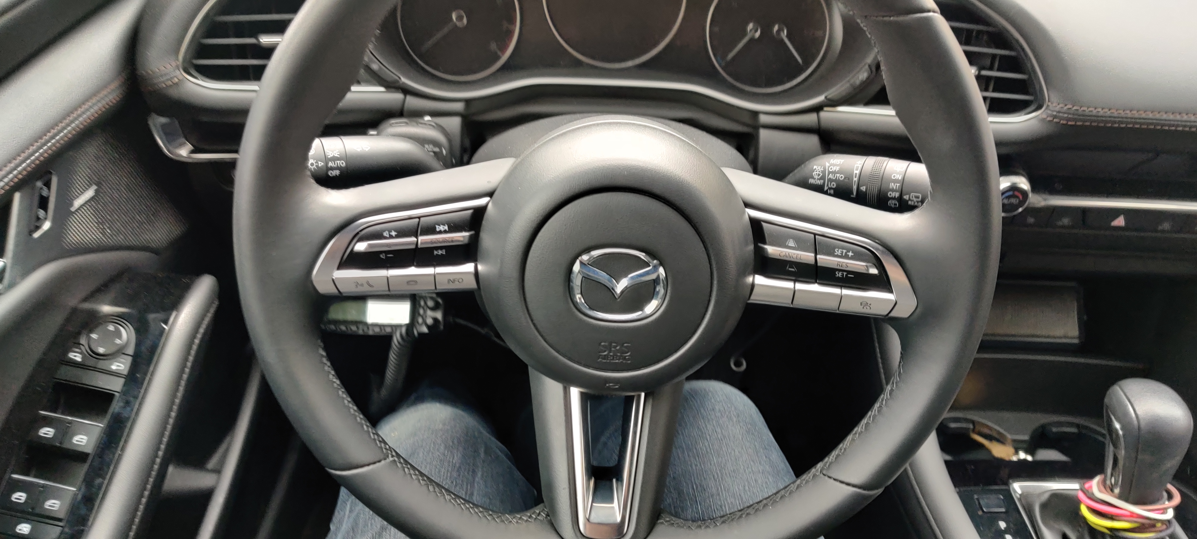
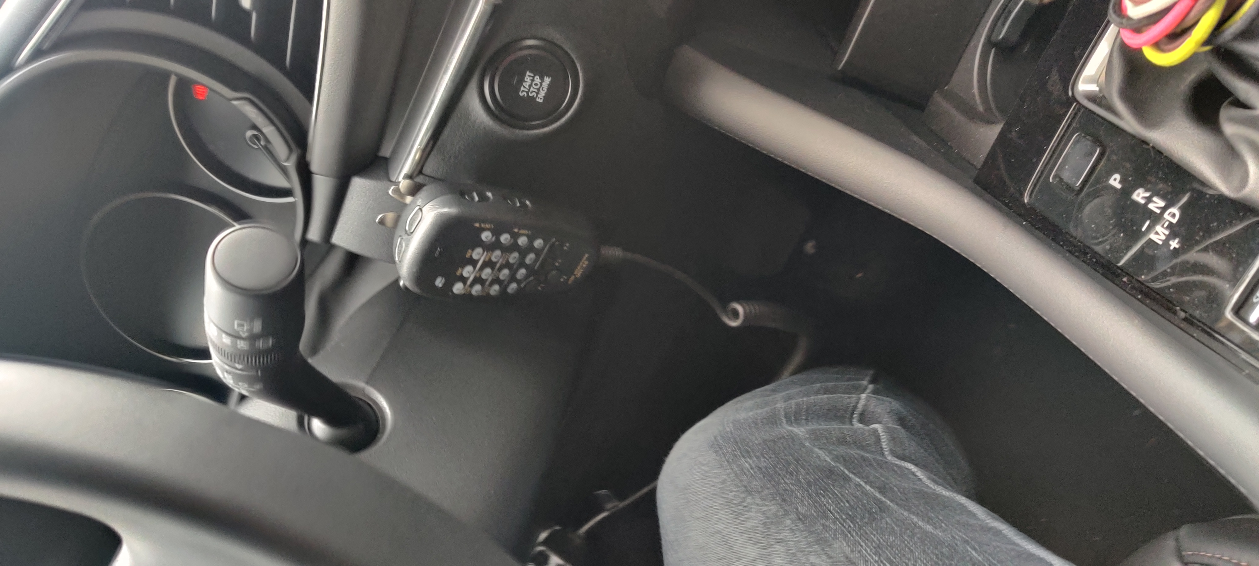
The cabling for that and the microphone for the FT-857D were pulled through the driver’s side door sills and up behind the inside OEM fuse panel. The FT-857D mic is the lesser-used one and got a clip on the left side of the steering wheel; the FT-8900R is the daily radio and got a clip on the right side next to the pushbutton start.
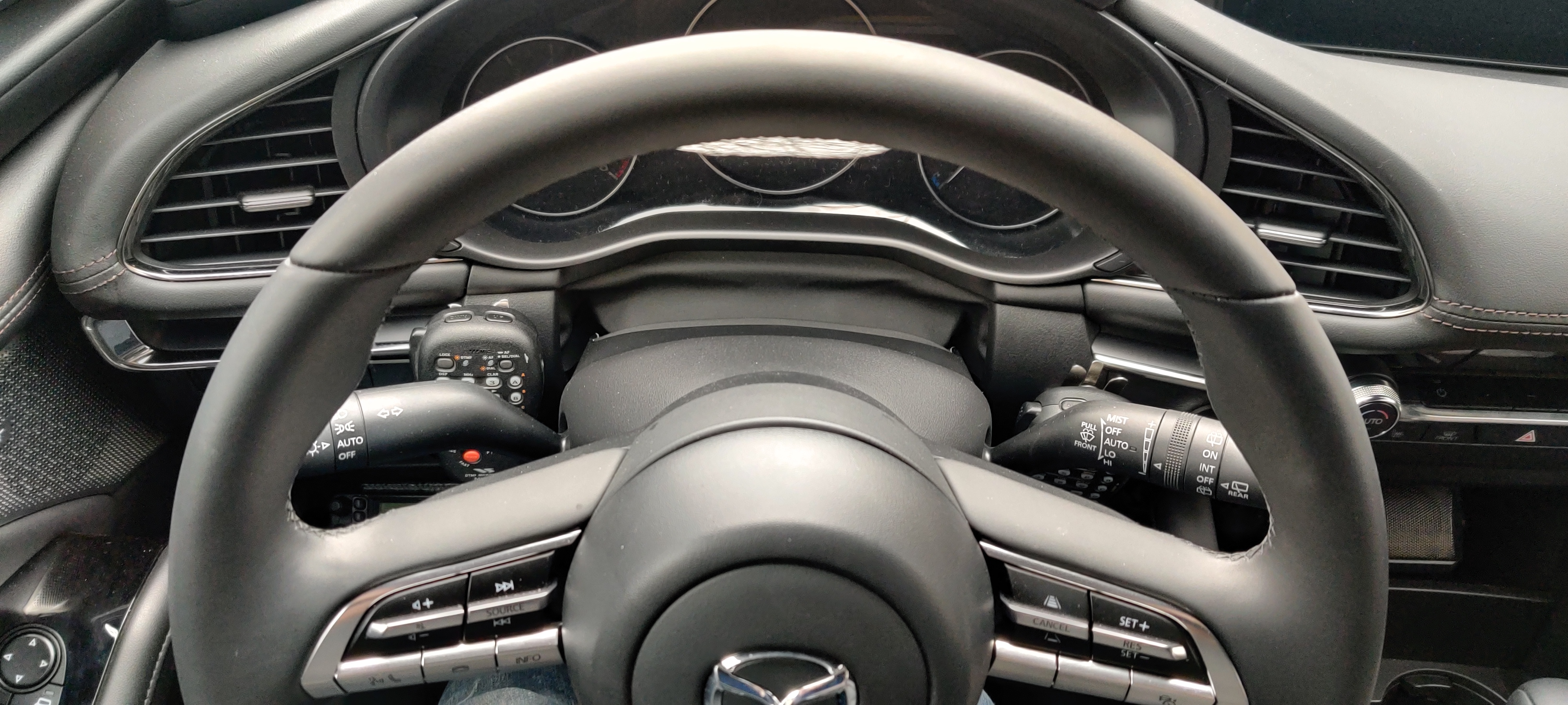
Overhead shot showing both mics nestled around the steering column.
Overhead shot showing both mics nestled around the steering column.

FT-8900R mic on right side of steering column, next to pushbutton ignition.
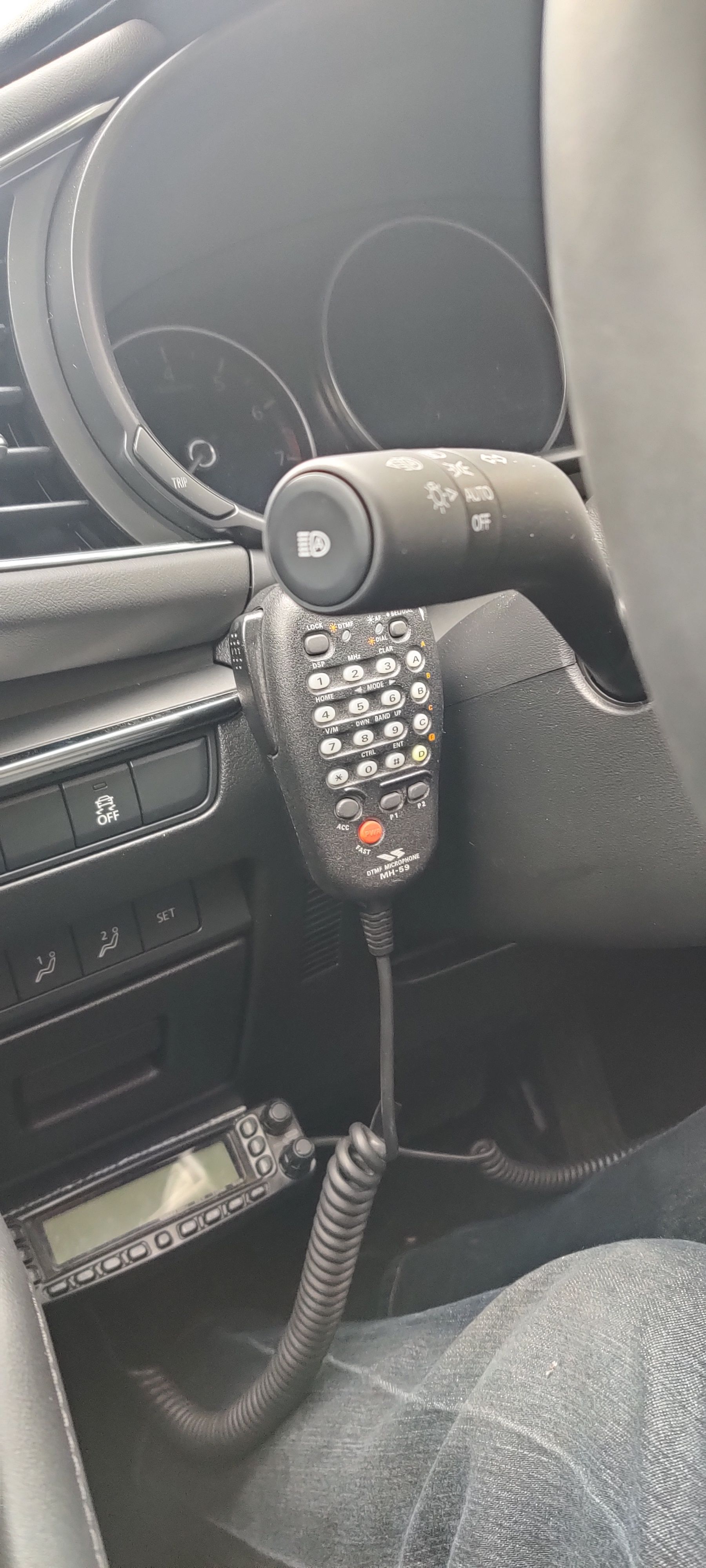
FT-8900R mic on right side of steering column, next to pushbutton ignition.

FT-857D mic on left side of steering column.

FT-857D mic on left side of steering column.

Now, where to put the FT-857D head? On Matilda, I mounted it front and center on the dash, just under the infotainment screen and vents. However, Minerva’s dash is laid out differently, the cupholders are up there in the way, and absolutely everything is covered in leather that I am loathe to drill holes in.

So I put the head in the much-expanded center console storage area. Some DualLock holds it to the wall, it is set low enough the console cover slides over cleanly, and just a little plastic notching and the cable runs cleanly under the trim panel, down the side of the console, and under the carpet under the driver’s seat to the door sills, where it joins its sister cabling back to the rear quarterpanels.
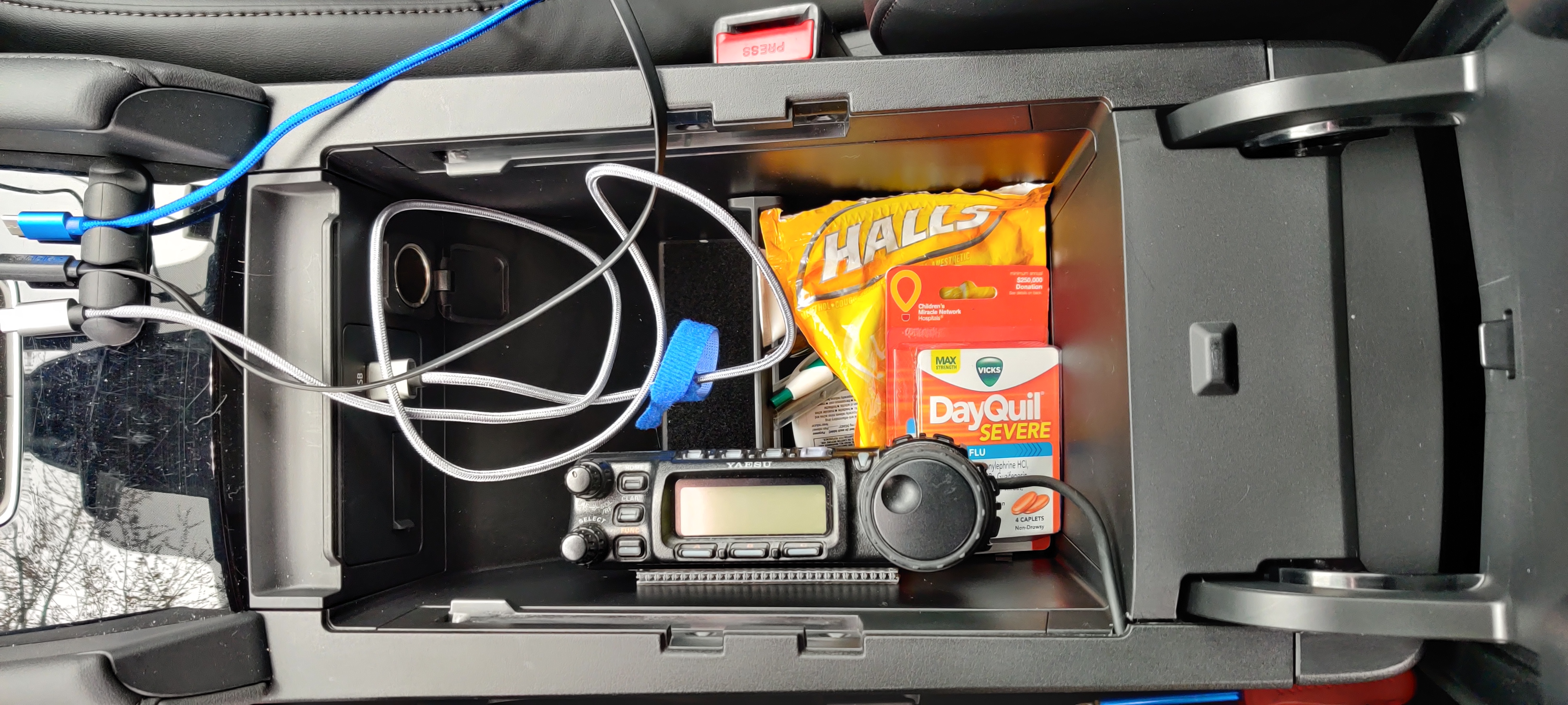
FT-857D head mounting inside center console storage bin. Note the one and only accessory port in the car, and the cable neatly going under the trim panel...

FT-857D head mounting inside center console storage bin. Note the one and only accessory port in the car, and the cable neatly going under the trim panel…
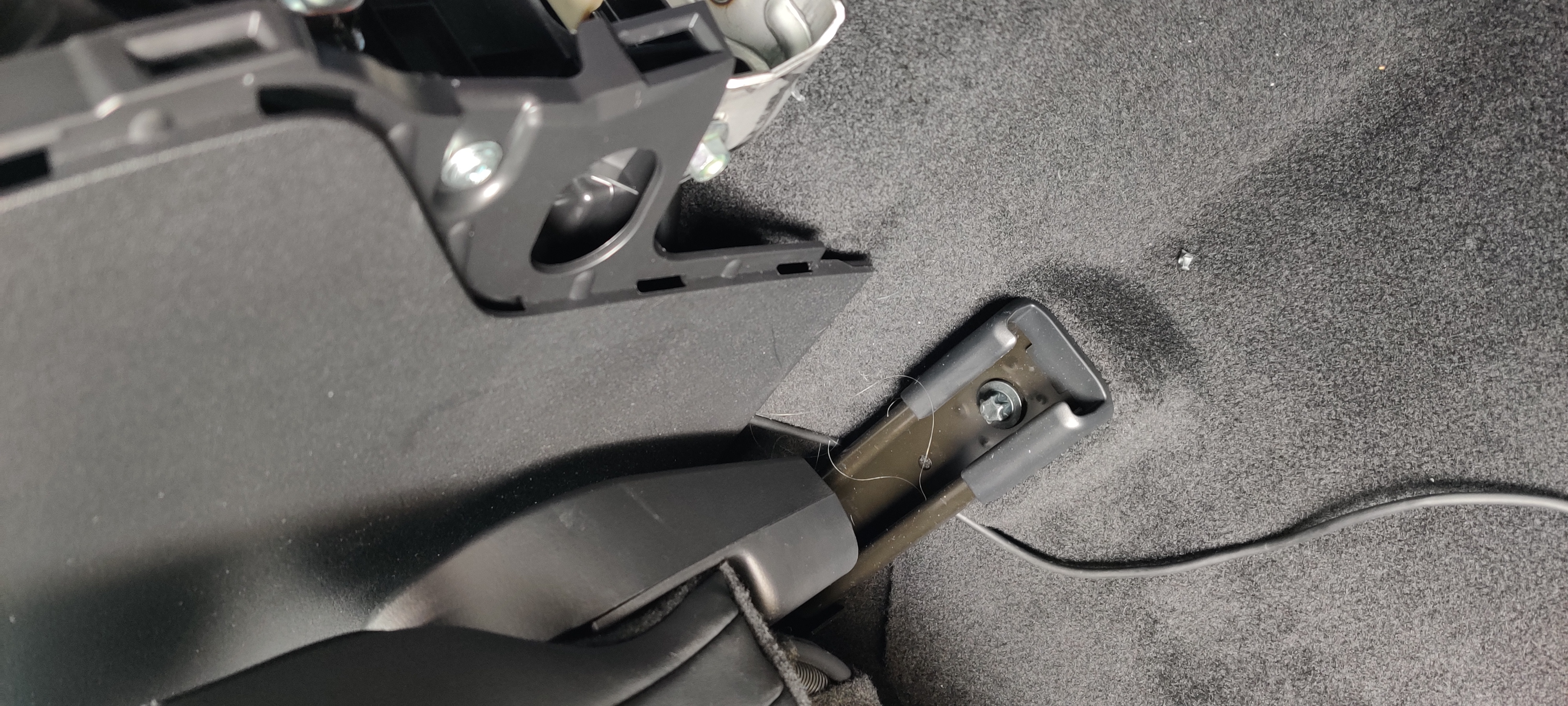
...which then runs down under the panel to the floor, to go under the driver's seat...

…which then runs down under the panel to the floor, to go under the driver’s seat…
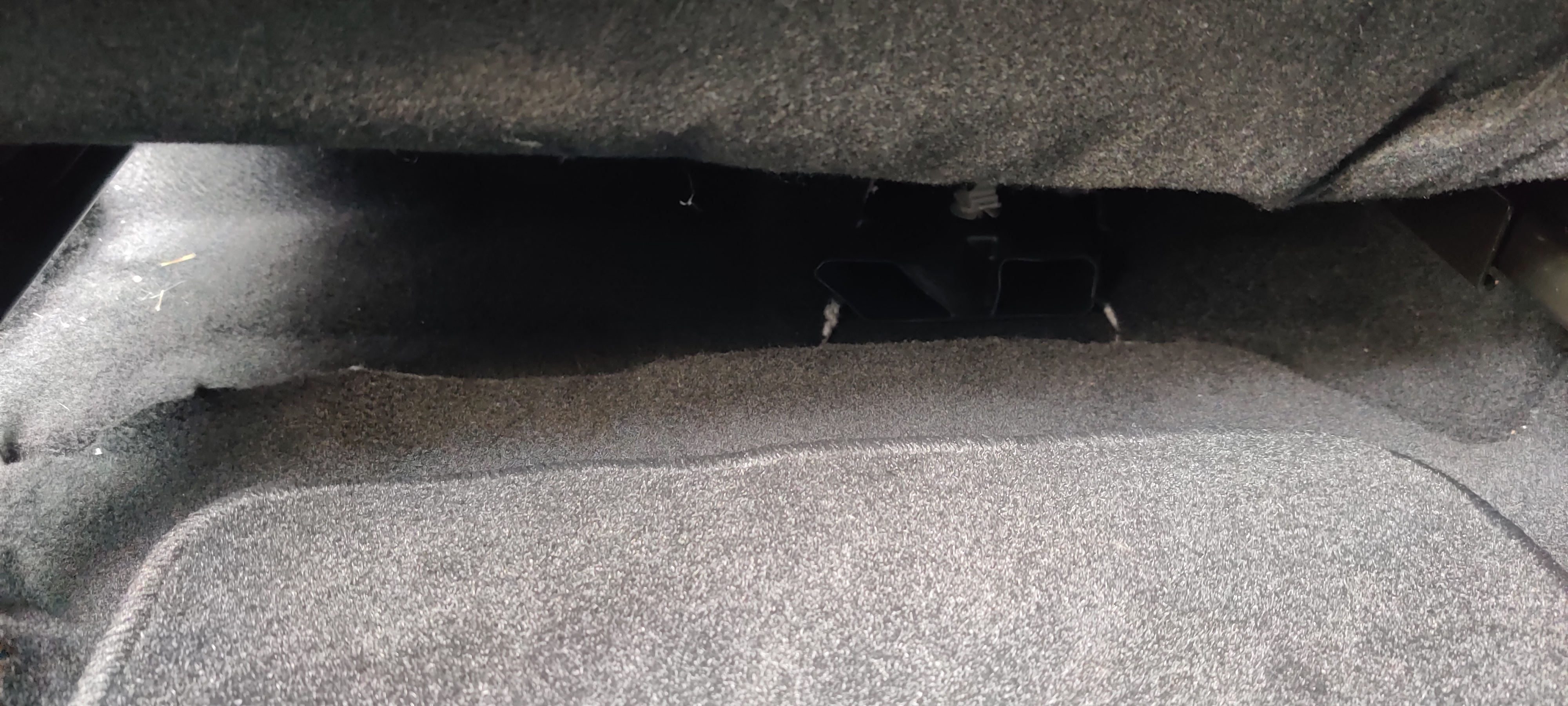
...and under the carpet under the seat to the door sill, where it heads back to the rear quarterpanels.

…and under the carpet under the seat to the door sill, where it heads back to the rear quarterpanels.

Speaker

With the radios hidden behind much of the soundproofing in the rear of the car, they really need an external speaker. On Matilda, I had this “hidden” behind the infotainment screen. However, again, Minerva’s dash is all leather and laid out differently, so that option is just bad.

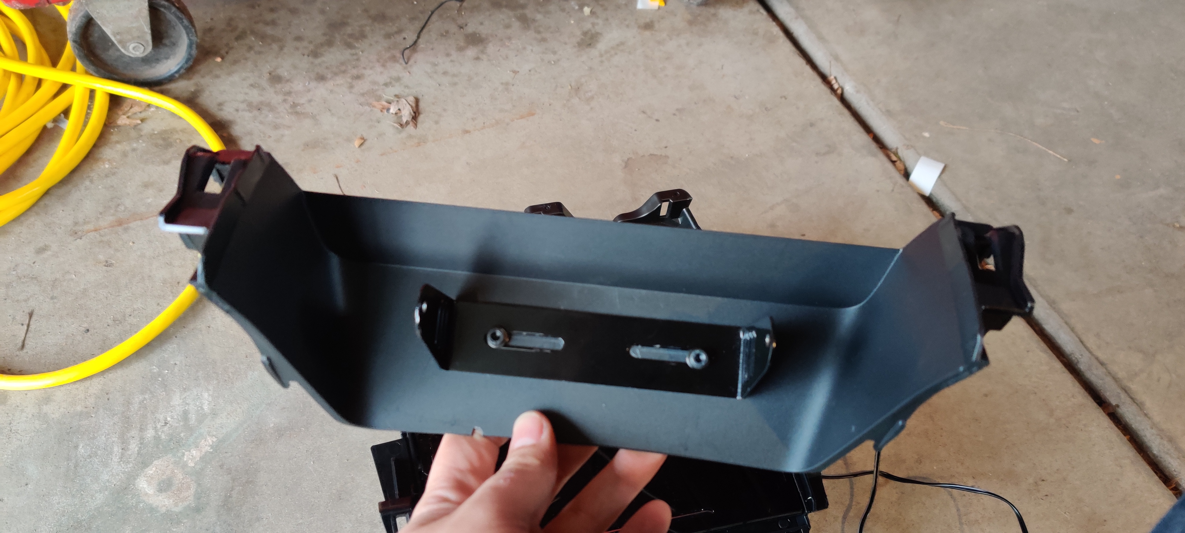
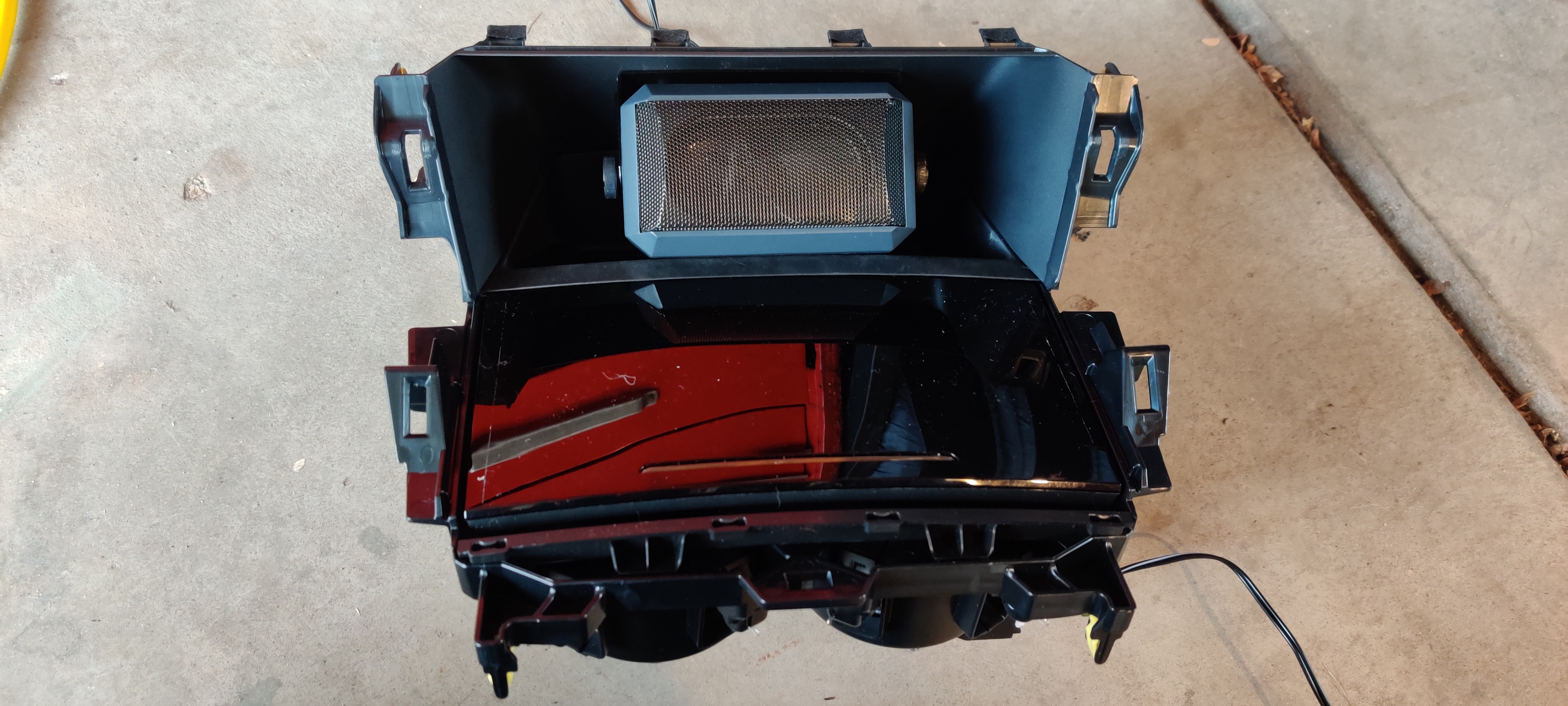
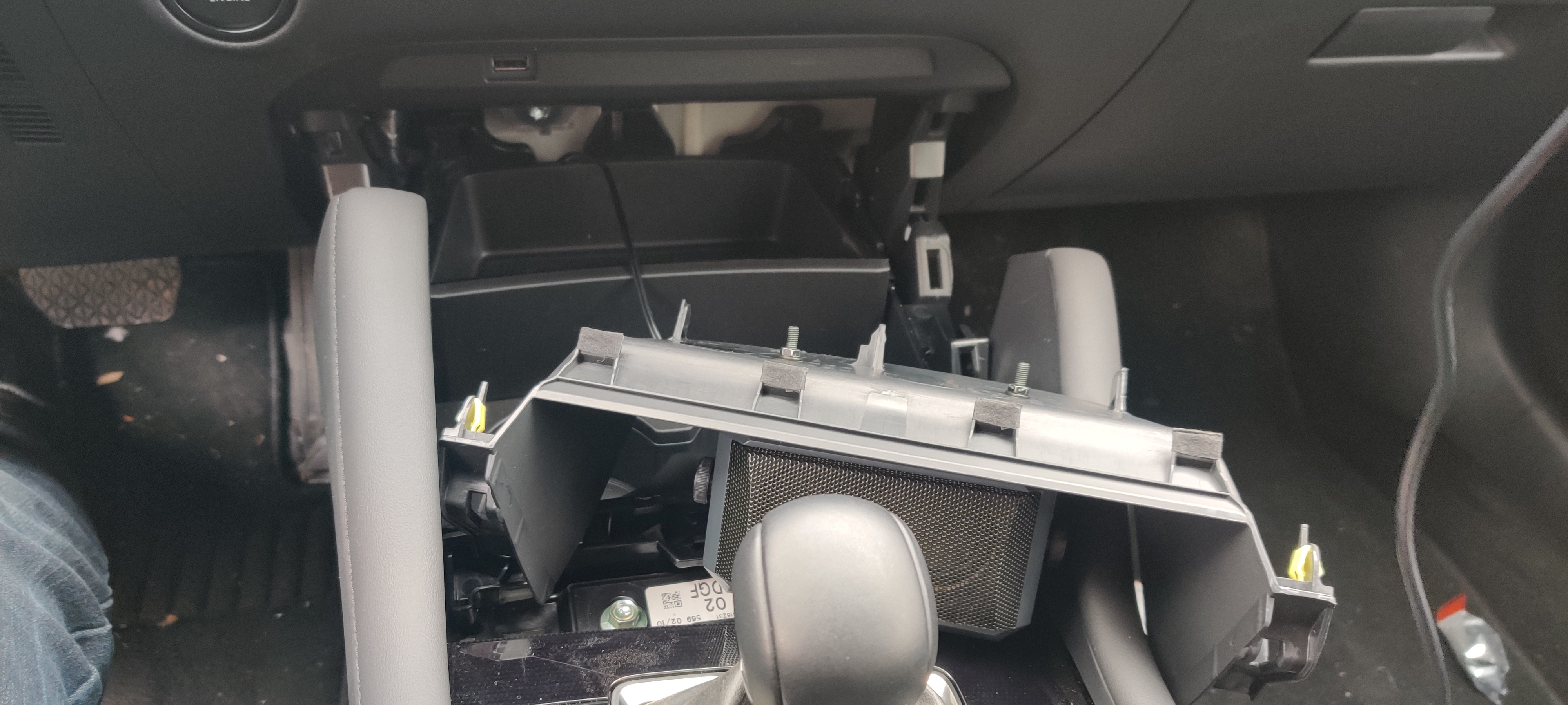
However, there is kind of a useless open storage area under the HVAC controls, forward of the cupholders. Some (OK, a lot) disassembly of the center console later, and I had the whole cupholder/storage/valence module out. A few holes drilled into the valence for the bracket, and another careful cable notch in the edge, and the whole thing reassembled into place. The cable runs through the console to meet up with the FT-857D head separation cable, and then back to the rear quarterpanels to meet the 1-2 switch (and eventually the mixer).
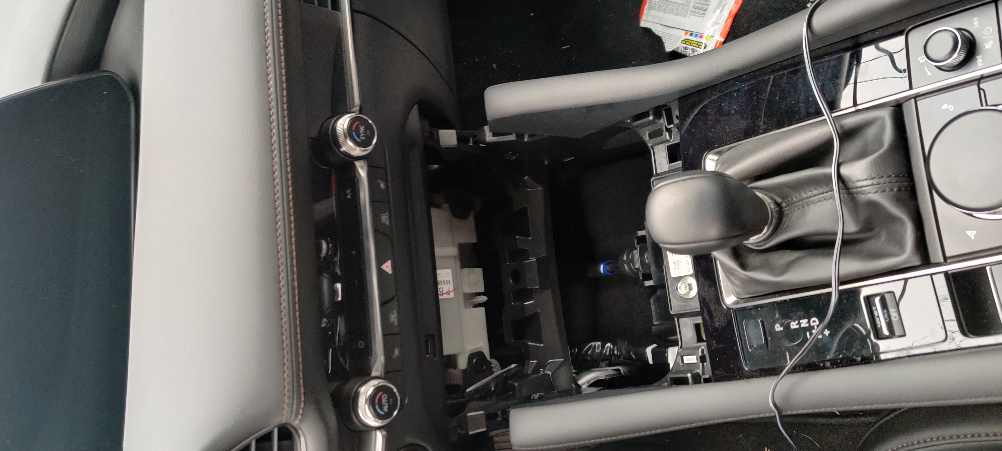
Center console with some disassembly.
Center console with some disassembly.

Bracket mounted on valence.
Bracket mounted on valence.

Cupholder module assembled with speaker installed.
Cupholder module assembled with speaker installed.

Cupholder reinstalled, working the valence with speaker into place.
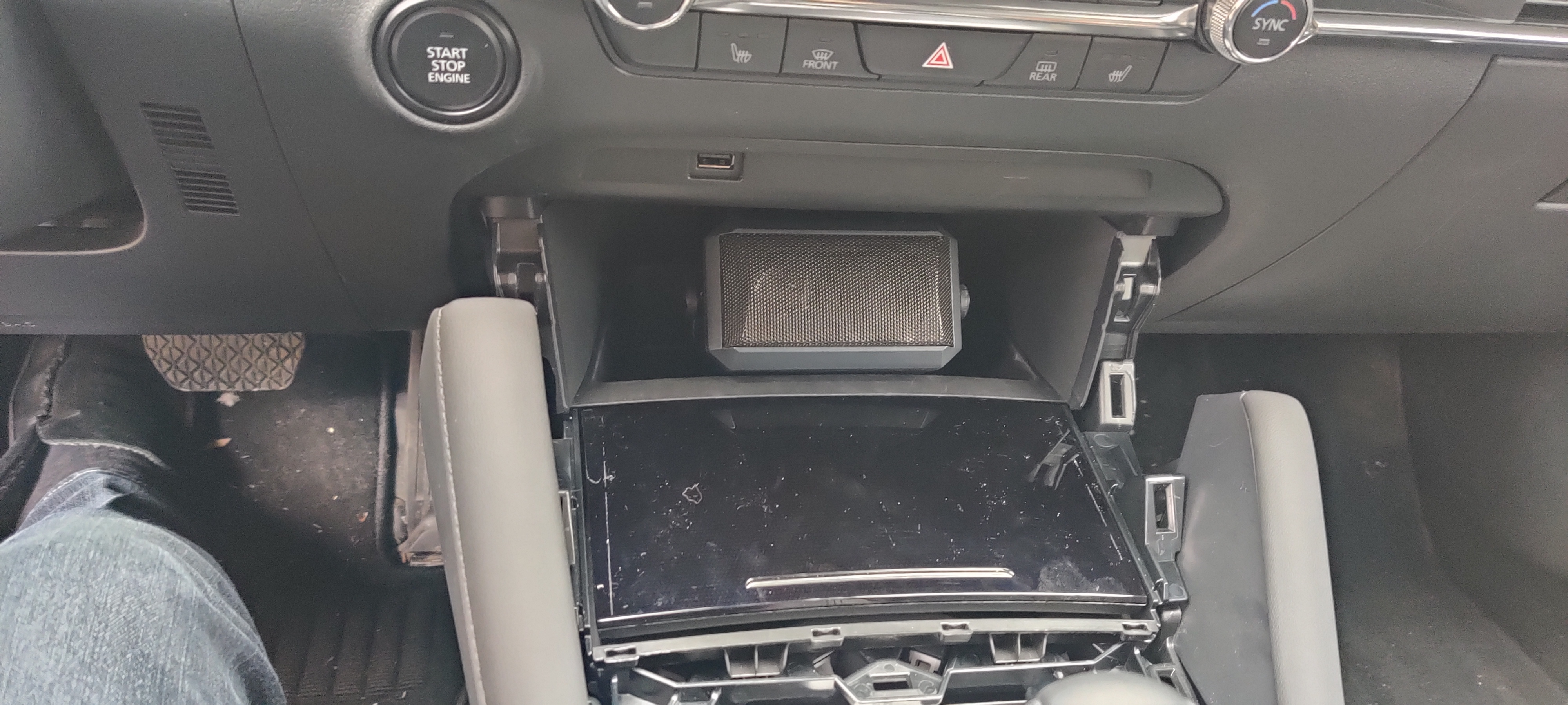
Cupholder reinstalled, working the valence with speaker into place.

Everything back into place, now to reassemble the console.
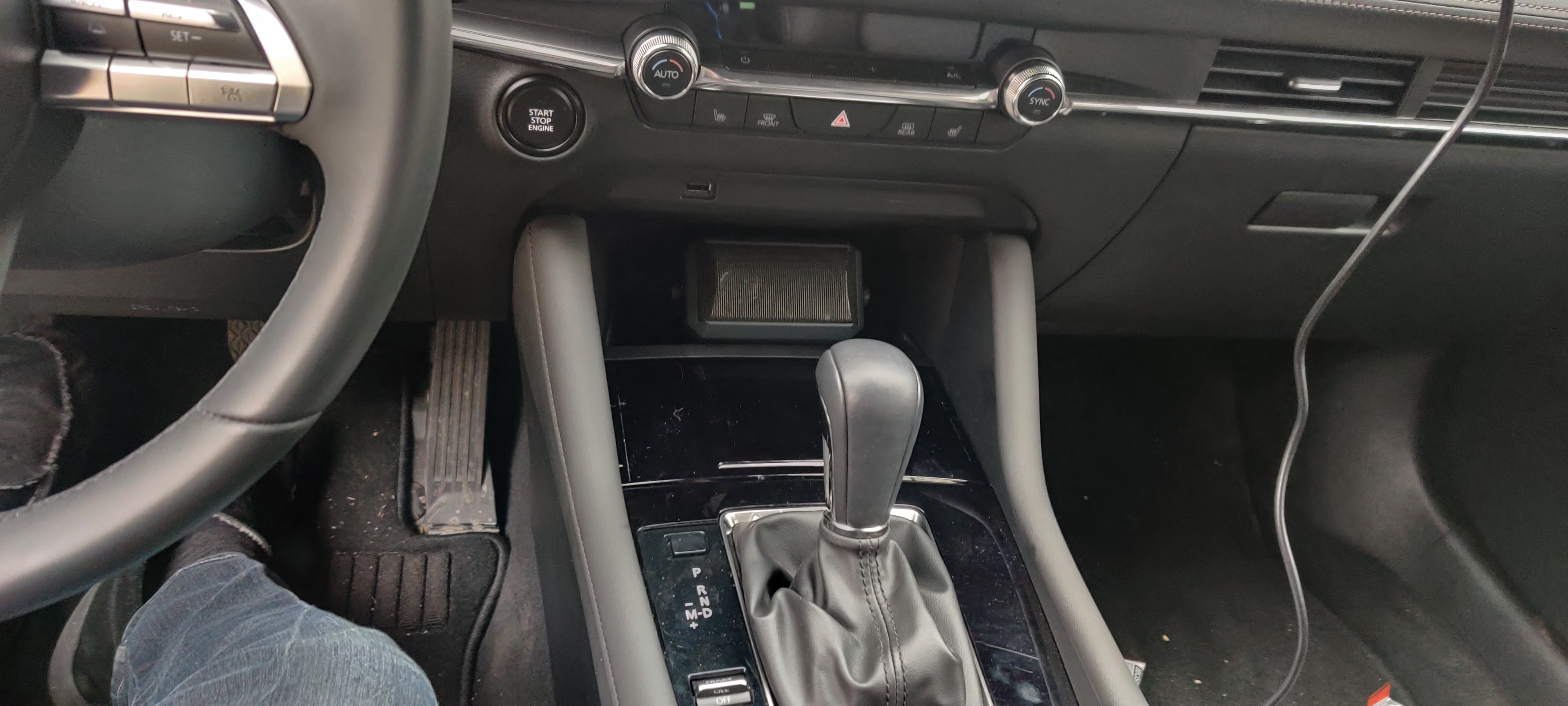
Everything back into place, now to reassemble the console.

Everything complete, cupholder door closed.
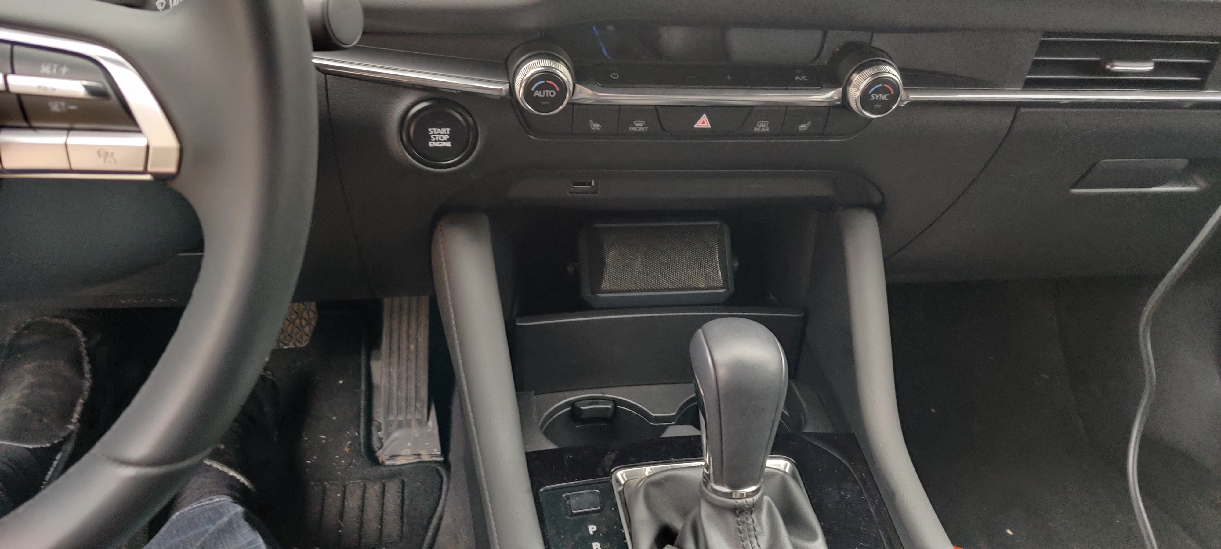
Everything complete, cupholder door closed.

And yes, of course the door opens and there is plenty of space for drinks.

And yes, of course the door opens and there is plenty of space for drinks.

Remaining Tasks

No project is ever finished. Next up for this one:

  1. Pack the mounts with dielectric waterproof grease (I do not trust some of the metal-on-metal seals in the mounts and I like automatic car washes)
  2. Find an SWR meter and retune the HV-7A for its new situation
  3. Install the mixer in place of the 1-2 switch
  4. Install the programming cable extension and Bluetooth adapter for the FT-857D
  5. Install the connector caps for car washes
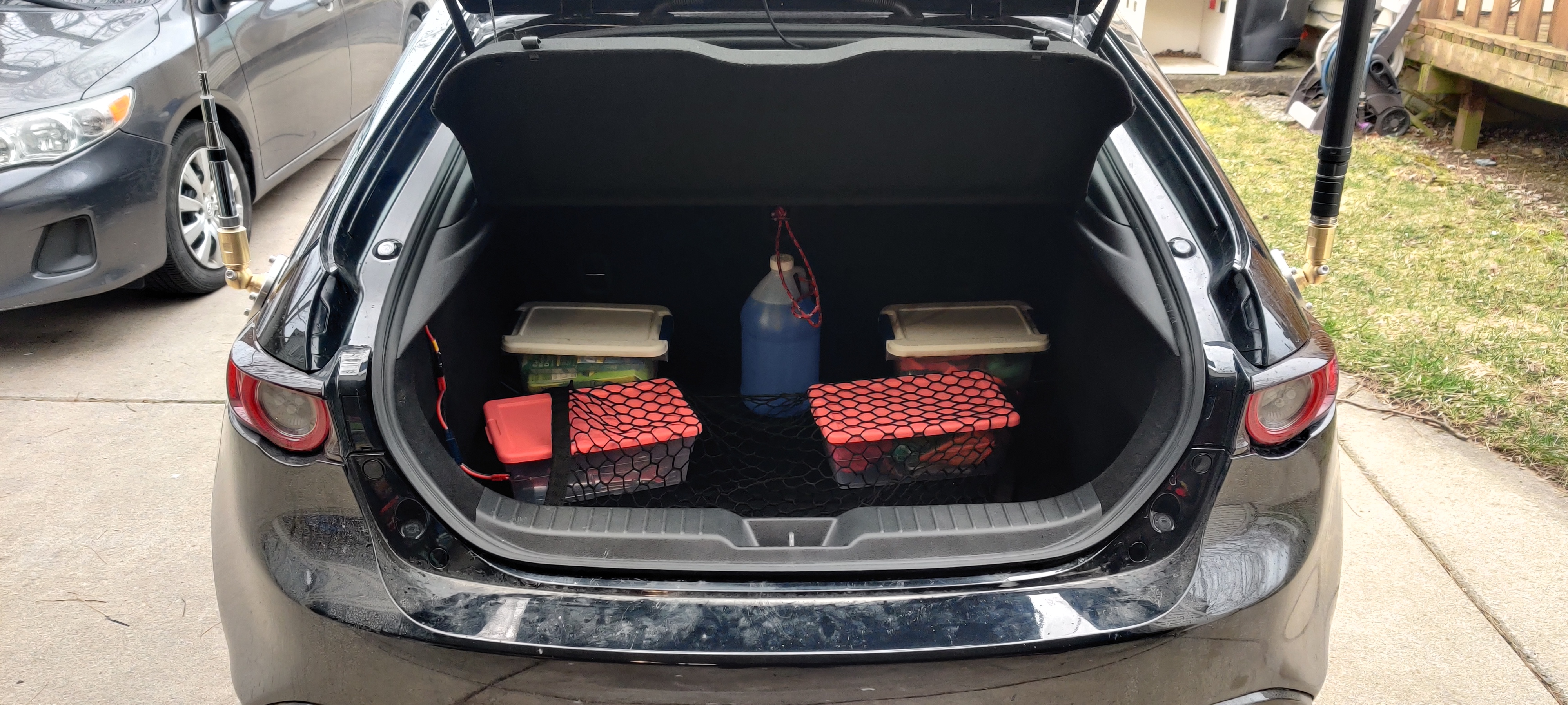
Cargo area fully buttoned up, showing both antennae.

Cargo area fully buttoned up, showing both antennae.

KE8HOJ mobile, 73 and clear!
Wayfarer “Magic Box” Replacement

Wayfarer “Magic Box” Replacement

Preamble

My dad has been an avid small-boat sailor for absolutely forever, with his dad taking him out for the first time in 1965 when he was 8 years old. He took to it like a duck to water (pun). Grandpa had purchased a 14′ daysailer made (at the time) by MFG, of a class called the Pintail (see, pun). Dad bought it off him in 1975. Dad started taking me out on his boat when I was about 6 months old, and I have deeply enjoyed it all my life as well.

As the story goes, he and the rest of the Pintails used to have to select race times and even lakes from a lottery, so large and myriad were the small-boat fleets in northern Oakland County in the late 1960s and 1970s. When Dad came back to SE MI a few decades later (after running about the world for work, then settling in Milwaukee and raising me and my brother), he discovered that the fleets were gone. He teamed up with the owner of Avon Sailboats to start a mixed-fleet casual racing fleet on Stony Creek Metropark, CreekFleet.

His dream the last decade has been to get into one-design racing, where all boats on a given starting line are of the same class. This means that positions crossing the finish line are the actual race results; no handicaps, no calculations in the committee room. He has been buying and selling as many Pintails as he can get his hands on, trying to bolster the fleet, since he and I are effective caretakers of the National Pintail Class Association. Trouble is, despite bringing 12 boats into the area, we can rarely attract more than a handful to race at a time.

This winter, he was approached by someone who wanted to get rid of a slightly larger boat called a Wayfarer (I bet you were wondering where I was going with this). The Wayfarer fleets in the US Midwest and all the way up into Toronto are enormously active, so this boat might finally be the chance to do one-design regattas like the Bayview One Design series or the Clark Lake Fall Regatta.

But of course there are downsides to cheap boats. This particular boat, sail #2413, had not only seen better days but also had never been raced. While the Wayfarer is a racing sloop, #2413 had spent the years since her hull was laid in 1970 as a cruising family boat, and she bore none of the fittings or controls that a racing boat of her class typically bears. While there are many further stories to tell about Wayfarer #2413, newly dubbed “THX 1138: Stay Calm.” (because my dad is a giant nerd and gave it all to me too), the particular one I am trying to get to here is that of the “magic box”.

Unlike a lot of other small racing sloops, the Wayfarer class does not tension the rig by tightening the forestay. Instead, the jib hoist is used to apply as much as 300-400 pounds of tension (sue me, I was raised in the US) to the rig. The issue is, #2413 being a cruiser, only had a bare halyard and the grunt of the crew (me) to put as much tension on it as she could (not much), hampered further by the routing of the free end of the halyard out of the bottom of the mast, through a turning block, and thus pulled upwards to tension relying then on the crew’s (me) muscles (very minimal especially after a year of HRT). Most racing Wayfarers either use a 40:1 block and tackle set to tension the halyard after the sail was hoist, or a worm-driven friction winch contraption affectionately dubbed a “magic box”.

Since dad was uncertain whether he would keep #2413, he was reluctant to put the kind of money into her just yet that either of those venerable solutions would run him. In addition, as a not-very-svelte, not-very-graceful crewmember, I disliked the solutions because they are bulky and liable to give me even more things to run into during fast racing maneuvers. Enter my replacement (finally!).

Design

I figured that a winning design needed to meet the following:

  1. Be cheap, preferably under $100 to replicate
  2. Be reasonably easy to make with common machine shop tools (though to be honest a CNC mill would have been helpful)
  3. Be compact, preferably protruding less than an inch into the cockpit from under the deck
  4. Mount along the side of the tabernacle, to catch the halyard as is dropped out of the bottom of the mast
  5. Be operable underway without power tools

As such, I ended up basing the design around an ACME leadscrew. Compact, inexpensive, and powerful, and driven easily by a socket and ratchet onboard (though a power drill on shore makes much quicker work of it). The system is self-contained, putting minimal force onto the old wood of the tabernacle, and protrudes barely enough for a socket to clear the drive nut. A basic metal lathe and manual mill are the only machines needed to make the custom parts, though of course CNC variants of either would turn out more consistent parts more quickly.

Custom Parts

There were a handful of custom parts that had to be produced, either from raw stock or as modifications to purchased components:

Bushing Blocks
Cut from 6061, these hold the brass bushings and support the leadscrew ends
Car
Cut from 6061, this encompasses the bronze ACME nut and rides along the leadscrew, carrying the V cleat and thus the free end of the halyard
Leadscrew
Turned from the leadscrew stock, one end is threaded for the 1/4-20 acorn nut, then cross-drilled for a roll pin to retain it. Both ends are turned to be a turning fit in the bushings.
Frame
Cut from the S/S angle, this piece serves as the backbone of the system, to put as little force into the tabernacle as possible

Purchased Components

Manufacture

Approximately 20 hours of my time went into the machining and assembly of the system, though I am a slow machinist so take that as it is.

Tooling Required

  • center drill or punch
  • deburring tool or file
  • drill for 6-32 tap
  • 6-32 bottoming tap
  • drill for 12-24 tap
  • 12-24 tap (1″ long cut, so maybe bottoming too?)
  • 1/4-20 die
  • 1/8″ carbide roundover router bit (edge break)
  • 1/4″ 82Ā° countersink
  • 3/8″ diameter 3/4″ cut length end mill, minimal radius
  • 1/2″ diameter end mill or counterbore
  • 1/8″ drill (roll pin rough)
  • 1/8″ reamer (roll pin fine)
  • 5/32″ drill (clearance for 6-32)
  • 25/64″ diameter 4″ length drill (leadscrew/bushing rough)
  • 3/8″ reamer (leadscrew/bushing fine)
  • fly cutter or shell mill
  • 1/8″ radius lathe tool, HSS or carbide

Process

Leadscrew

I turned the bushing seats first, then further reduced a section on one end to the threading diameter for a 1/4-20 die. Then I hand-threaded it with a die; I hate cutting small threads on the Acer.


One exciting and unexpected incident was that the length of leadscrew was slightly longer than the Acer can turn in a stable fashion, and so suddenly the section in the spindle bore threw itself to one side and violently shook until I could stop the lathe. As a result, my leadscrew is slightly bowed. I fixed this by wadding it up with shop towels until it was a snug fit, and that kept things true for the rest of the cutting work.

Bushing Blocks

I squared up the piece of 6061 that would become both blocks and the car, then indicated it in clamping in a square fixture and the vice with the long axis vertical. Then I drilled and reamed for the leadscrew clearance hole all the way through the piece — pair drilling in the finest form!


After this, I parted off the rough thicknesses for the blocks on the bandsaw, then took them to final dimensions with a shell mill. I picked up the bore with an indicator, and counterbored one face on each block for the flange of the bushing.

I drilled and tapped the two 6-32 holes on the bottom of each block, then stamped a “T” and a “B” into each, to aid in reassembly (top and bottom block, stamps face the same way). Then I shaped the top curve on the belt sander, smoothed the cutter marks on a Scotchbrite wheel, then polished with a medium grit polish and buffer.

A light press on the Arbor press set the bushings in place at depth, and the leadscrew ran smoothly in each block. I did end up coming in and reaming the bushings back to 0.2510″, because installed on the frame, the leadscrew’s gentle curve jammed the system at certain points.

Car

Once parted from the bushing blocks above, much the same treatment was done: cut to final dimensions on the shell mill, drilled and tapped the 12-24 holes for the V cleat. However, I also carefully slotted the side to encompass the bronze nut firmly and centered on the reamed bore.

To dress and break the edges, I used a carbide 1/8″ round over router bit on the highest speed the old Bridgeport spindle can reach (about 2500rpm). Cut like a dream with a little Tap Magic. Once softened, the same Scotchbrite and polish steps were performed.

Frame

The frame was simple: On each of the two faces in turn, zero the DRO on the corner as a datum, then center drill and drill each hole per the face’s hole chart, countersinking as needed. Two tapped holes did get the better of me, but I was using cheap carbon steel taps from Lowe’s so this was more or less expected.

Bench Testing

I had to test, of course!

Tensioning Test
Relax and Break Test

Deviations

  1. Had to replace the 6-32 fasteners for the block attachment fitting with 1/4-20 points because I broke off the 6-32 tap in those holes.
  2. Had to ream the bushings because the leadscrew is slightly bent due to the incident above.

Installation

Mark the top hole, ensuring that the upper end of the frame is secure against the bottom of the deck, there is clearance for the 7/16″ socket to drive the acorn nut, and the lower end is flush with the aft side of the tabernacle. Drill a hole through the tabernacle large enough for the shaft of the tee nut. Install the tee nut and clamp down to set it using a strong clamp. Install a 6-32 1.25″ screw and mark the remainder of the five mounting holes. Remove the screw and drill those, then reinstall all five screws into their respective tee nuts.

Our connecting link had an opening too small to fit over our lacing eye, so we just leave the RF280 captive by a stop knot on the halyard. To rig, once the mast is up, simply drop the block’s loop into the connecting link and secure, then hoist the jib normally. Once taut, set the halyard into the V cleat and tension using the screw.

Use

Testing

The day before Clark Lake, we fitted the system to the tabernacle and put tension to the rig for the first time. 125 pounds, easy, and hardly any backpressure on the ratchet handle. The forestay went slack as it was supposed to, the rig being held by the halyard.


Clark Lake Regatta 2019-09-21

The local newspaper for the lake did a really nice two-part write up on the regatta this weekend. Dad and I took ninth place overall out of 12 boats in our class:
Part one, for Saturday 2019-09-21, and Part two, for Sunday, 2019-09-22.

Thoughts / Lessons Learned

The system works well, though 12tpi means lots and lots of turning. A power drill or screwdriver is recommended for shore work. The system stays nicely out of the way during even heavy air sailing (I have many bruises, but none of them from the tensioning system).

All CAD files, in both original Autodesk Inventor 2019 (*.ipt) and IGES interchange (*.igs) formats, as well as 2D prints for the custom parts in both DXF and PDF, can be found on this project’s Thingiverse page. This allows for downloading, editing, and commenting for changes.

Happy sailing!

MadridCrafted Bathymetric Maps: i3 member projects at Maker Faire Detroit

Maker Faire Detroit returns to the Henry Ford on July 27th and 28th, and as always, numerous projects by i3Detroit members will be on display. Among them, Dan Madrid’s laser-cut bathymetric maps:

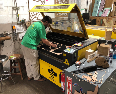
Dan Madrid laser cutting bathymetric maps

Dan Madrid works at the Bumblebee laser

For the past several months, Dan has been a frequent sight in front of i3’s laser cutters, making plywood representations of the lakes we all know and love. It started as a hobby project, but he soon started getting requests and selling his work, following a path familiar to many of i3’s members. He’s started a small business called Madrid Crafted LLC, and most of his work is Michigan-focused.

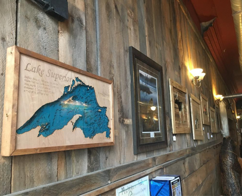
As an MTU grad and still a frequent visitor to the UP, Dan’s most popular piece by far is Lake Superior, shown here on the wall of the Keweenaw Brewing Company tap room in Houghton:

Lake Superior bathymetric map on the wall at KBC

Lake Superior bathymetric map on the wall at KBC

But Dan wasn’t always an i3Detroit member ā€” as a Ford employee, his first experience of one of his remote jobs with laser-cut art was at TechShop. “They had a great woodshop, but what really hit me was the laser cutters.” The experience was eye-opening, but short-lived. After TechShop closed in late 2017, he searched for another nearby makerspace, and found The Village Workshop in Northville, close to his home in Livonia. There, woodworking and laser-cutting went from a hobby to a real side business, but The Village Workshop likewise shut down in early 2019. Dan went on the search again and found i3Detroit, a longer drive but a totally different community.

“Techshop and The Village Workshop were great places, I don’t want to disparage them, but when I came here there was a much greater sense of community. There it was much more like a business transaction, like I pay you, and I get access to your shop. There wasn’t ā€” at least when I was there ā€” there wasn’t much of a community aspect. When I came here, people come here to do projects, but they also come here to build relationships with the other people here. I didn’t experience that at the other places. … I know I see other people working on things and I know I can ask, hey what’s that? And that sparks some curiosity and discussion.”

That community is what drove Dan to show off his work at Maker Faire for the first time: “Having started a small business, my goal this year was to go to one farmer’s market, fair, something like that. And the nice thing is, there’s a community aspect to this, so it’s not just me finding a place on my own and figuring it out, we get to do it together.”